CDB5534U Cirrus Logic Inc, CDB5534U Datasheet - Page 45
CDB5534U
Manufacturer Part Number
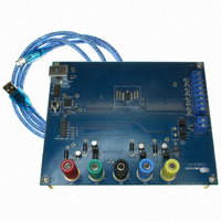
CDB5534U
Description
EVAL BOARD FOR CS5534
Manufacturer
Cirrus Logic Inc
Specifications of CDB5534U
Number Of Adc's
1
Number Of Bits
24
Sampling Rate (per Second)
3.84k
Data Interface
Serial
Inputs Per Adc
2 Single
Input Range
0 ~ 2.5 V
Power (typ) @ Conditions
35mW @ 5 V
Voltage Supply Source
Analog and Digital, Dual ±
Operating Temperature
-40°C ~ 85°C
Utilized Ic / Part
CS5534
Description/function
Audio DSPs
Operating Supply Voltage
5 V
Product
Audio Modules
For Use With/related Products
C8051F320
Lead Free Status / RoHS Status
Contains lead / RoHS non-compliant
Lead Free Status / RoHS Status
Lead free / RoHS Compliant, Contains lead / RoHS non-compliant
Other names
598-1016


SDI - Serial Data Input.
SDO - Serial Data Output.
SCLK - Serial Clock Input.
A0 - Logic Output (Analog)/Guard, A1 - Logic Output (Analog).
Measurement and Reference Inputs
AIN1+, AIN1-, AIN2+, AIN2- AIN3+, AIN3-, AIN4+, AIN4- - Differential Analog Input.
VREF+, VREF- - Voltage Reference Input.
C1, C2 - Amplifier Capacitor Inputs.
Power Supply Connections
VA+ - Positive Analog Power.
VD+ - Positive Digital Power.
VA- - Negative Analog Power.
DGND - Digital Ground.
DS289F5
SDI is the input pin of the serial input port. Data will be input at a rate determined by SCLK.
A clock signal on this pin determines the input/output rate of the data for the SDI/SDO pins
respectively. This input is a Schmitt trigger to allow for slow rise time signals. The SCLK pin
will recognize clocks only when CS is low.
The logic states of A1-A0 mimic the OL1-OL0 bits in the selected Setup, or the A1-A0 bits in
the Configuration Register, depending on the state of the OLS bit in the Configuration Register.
Logic Output 0 = VA-, and Logic Output 1 = VA+. Alternately, A0 can be used as a guard drive
for the instrumentation amplifier with proper setting of the GB bit in the Configuration Register.
Differential input pins into the device.
Fully differential inputs which establish the voltage reference for the on-chip modulator.
Connections for the instrumentation amplifier’s capacitor.
Positive analog supply voltage.
Positive digital supply voltage (nominally +3.0 V or +5 V).
Negative analog supply voltage.
Digital Ground.
SDO is the serial data output. It will output a high impedance state if CS = 1.
CS5531/32/33/34-AS
45
Related parts for CDB5534U
Image
Part Number
Description
Manufacturer
Datasheet
Request
R

Part Number:
Description:
Development Kit
Manufacturer:
Cirrus Logic Inc
Datasheet:
Part Number:
Description:
Development Kit
Manufacturer:
Cirrus Logic Inc
Datasheet:


Part Number:
Description:
High-efficiency PFC + Fluorescent Lamp Driver Reference Design
Manufacturer:
Cirrus Logic Inc
Datasheet:
Part Number:
Description:
Development Kit
Manufacturer:
Cirrus Logic Inc
Datasheet:
Part Number:
Description:
Development Kit
Manufacturer:
Cirrus Logic Inc
Datasheet:

Part Number:
Description:
Development Kit
Manufacturer:
Cirrus Logic Inc
Datasheet:
Part Number:
Description:
Development Kit
Manufacturer:
Cirrus Logic Inc
Datasheet:
Part Number:
Description:
Development Kit
Manufacturer:
Cirrus Logic Inc
Datasheet:
Part Number:
Description:
Development Kit
Manufacturer:
Cirrus Logic Inc
Datasheet:

Part Number:
Description:
EVALUATION BOARD FOR CS8427
Manufacturer:
Cirrus Logic Inc
Datasheet:

Part Number:
Description:
BOARD EVAL FOR CS8416 RCVR
Manufacturer:
Cirrus Logic Inc
Datasheet:

Part Number:
Description:
EVALUATION BOARD FOR CS8420
Manufacturer:
Cirrus Logic Inc
Datasheet:

Part Number:
Description:
KIT DEVELOPMENT EP9315 ARM9
Manufacturer:
Cirrus Logic Inc
Datasheet:

Part Number:
Description:
KIT DEVELOPMENT EP9302 ARM9
Manufacturer:
Cirrus Logic Inc
Datasheet: