SSM2306-MINI-EVALZ Analog Devices Inc, SSM2306-MINI-EVALZ Datasheet - Page 3
SSM2306-MINI-EVALZ
Manufacturer Part Number
SSM2306-MINI-EVALZ
Description
BOARD EVAL FOR SSM2306-MINI
Manufacturer
Analog Devices Inc
Specifications of SSM2306-MINI-EVALZ
Design Resources
Analog Audio Input, Class-D Output with ADAU1701, SSM2306, and ADP3336 (CN0162)
Amplifier Type
Class D
Output Type
2-Channel (Stereo)
Max Output Power X Channels @ Load
2.4W x 2 @ 4 Ohm
Voltage - Supply
2.5 V ~ 5 V
Operating Temperature
-40°C ~ 85°C
Board Type
Fully Populated
Utilized Ic / Part
SSM2306
Lead Free Status / RoHS Status
Lead free / RoHS Compliant


EVALUATION BOARD HARDWARE
Note that the SSM2306 evaluation board and layout guidelines
were developed by Gang Liu of Analog Technologies, Inc.,
Sunnyvale, CA.
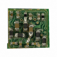
The SSM2306 mini evaluation board features the SSM2306
filterless, Class-D stereo amplifier, designed to drive a bridge-
tied load (BTL) stereo loudspeaker in portable audio applica-
tions. The SSM2306 mini evaluation board operates from a dc
power supply that can provide 2.5 V to 5.5 V. The audio input
source is amplified to drive 1.4 W into an 8 Ω loudspeaker at
5.0 V supply. The SSM2306 mini evaluation board accepts
differential or single-ended input signals.
On the left side of the SSM2306 mini evaluation board are five
solder pads for the input audio signal: INR+ and INR− for the
right channel, INL+ and INL− for the left channel, and GND
(see Figure 4). The evaluation board uses INx+ and INx− to
receive audio signals from common appliances, such as DVD
players, PCs, and TVs.
When the input signal is sensed in single-ended mode, the
single audio signal is transmitted from INR+ and/or INL+ into
the IC. For single-ended mode, the negative input nodes (INR−
and/or INL−) must be short-circuited to a neighboring ground
(see the schematic in Figure 3). Because some appliances have
strong ground noise, using only INR+ and/or INL+ as the inputs
may allow this noise to be converted into audible hissing sounds
at the output. If this problem occurs, a differential mode conn-
ection is needed to cancel the ground noise interference.
GETTING STARTED
To ensure proper operation, connect the loads immediately
after the ferrite beads using the OUTBL+, OUTBL−, OUTBR+,
and OUTBR− nodes.
WHAT TO TEST
When implementing the SSM2306 mini evaluation board in
your design, test the evaluation board for the following items:
•
•
•
•
•
•
Electromagnetic interference (EMI). Connect wires for the
speakers in the same length as for the actual application
and perform the EMI test.
Signal-to-noise ratio (SNR).
Total harmonic distortion + noise (THD + N).
Output noise. Use an A-weighting filter to filter the output
before the measurement meter.
Maximum output power.
Efficiency.
Rev. 0 | Page 3 of 8
COMPONENT SELECTION
Selecting the right components is the key to achieving the
performance required at the budgeted cost.
Input Coupling Capacitors
The input coupling capacitors, C1, C2, C3, and C4, should be
large enough to couple the low frequency signal components in
the incoming signal and small enough to filter out unnecessary
low frequency signals. For music signals, the selected cutoff
frequency is often between 20 Hz and 30 Hz. The value of the
coupling capacitor is calculated as follows:
where R = 43 kΩ + R
Input Series Resistors
Resistors in series with the input pins are not necessary
components for amplifier operation and are needed only when
special gain values are required. Using resistors with too high a
value increases the input noise.
Output Beads
The output beads, B1, B2, B3, and B4, are necessary components
for filtering out the EMI caused at the switching output nodes
when the length of the speaker wire is greater than 10 cm. The
penalty for using ferrite beads for EMI filtering is slightly worse
noise and distortion performance at the system level due to the
nonlinearity of the beads.
Ensure that these beads have enough current conducting
capability while providing sufficient EMI attenuation. The
current rating needed for an 8 Ω load is approximately 600 mA,
and impedance at 100 MHz must be > 220 Ω. In addition, the
lower the dc resistance (DCR) of these beads, the better for
minimizing their power consumption. Table 1 describes the
recommended beads.
Table 1. Recommended Output Bead
Part Number
MPZ1608S221A
Output Shunting Capacitors for the Beads
The output shunting capacitors for the beads, C5, C6, C7, and
C8, filter out lower frequency EMI ≤250 MHz. Use small size
(0603 or 0402) multilayer ceramic capacitors made of X7R or
C0G (NP0) materials. The higher the value of these capacitors,
the lower the residual EMI level at the output, and the higher
the quiescent current at the power supply. It is recommended
that 500 pF to 1 nF capacitors be used.
C = 1/(2π × R × f
Manu-
facturer
TDK
EXT
c
)
and f
Z (Ω)
220
c
is the cutoff frequency.
EVAL-SSM2306-MINI
I
(mA)
2000 0.05
MAX
DCR
(Ω)
Size (mm)
1.6 × 0.8 × 0.8
Related parts for SSM2306-MINI-EVALZ
Image
Part Number
Description
Manufacturer
Datasheet
Request
R

Part Number:
Description:
BOARD EVAL FOR SSM2306
Manufacturer:
Analog Devices Inc
Datasheet:

Part Number:
Description:
2 W, Filterless, Class-D Stereo Audio Amplifier
Manufacturer:
AD [Analog Devices]
Datasheet:

Part Number:
Description:
±1.7g Dual-Axis IMEMS Accelerometer Evaluation Board
Manufacturer:
Analog Devices Inc
Datasheet:

Part Number:
Description:
Inertial Sensor Evaluation System
Manufacturer:
Analog Devices Inc
Datasheet:
Part Number:
Description:
Manufacturer:
Analog Devices Inc
Datasheet:
Part Number:
Description:
Manufacturer:
Analog Devices Inc
Datasheet:
Part Number:
Description:
Manufacturer:
Analog Devices Inc
Datasheet:
Part Number:
Description:
Manufacturer:
Analog Devices Inc
Datasheet:
Part Number:
Description:
Manufacturer:
Analog Devices Inc
Datasheet:
Part Number:
Description:
Manufacturer:
Analog Devices Inc
Datasheet:
Part Number:
Description:
Manufacturer:
Analog Devices Inc
Datasheet:
Part Number:
Description:
Manufacturer:
Analog Devices Inc
Datasheet:
Part Number:
Description:
Manufacturer:
Analog Devices Inc
Datasheet: