MCP1630DM-DDBS2 Microchip Technology, MCP1630DM-DDBS2 Datasheet - Page 10
MCP1630DM-DDBS2
Manufacturer Part Number
MCP1630DM-DDBS2
Description
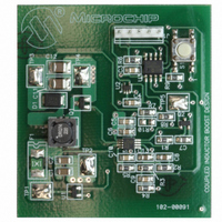
BOARD DEMO BOOST COUPLED INDUCTR
Manufacturer
Microchip Technology
Type
DC/DC Switching Converters, Regulators & Controllersr
Specifications of MCP1630DM-DDBS2
Main Purpose
DC/DC, Step Up
Outputs And Type
1, Non-Isolated
Voltage - Output
15 ~ 40V
Current - Output
30mA
Voltage - Input
3 ~ 5.5V
Regulator Topology
Boost
Frequency - Switching
100kHz
Board Type
Fully Populated
Utilized Ic / Part
MCP1630
Output Voltage
15 V to 40 V
Product
Power Management Modules
For Use With/related Products
MCP1630, PIC12F683
Lead Free Status / RoHS Status
Not applicable / Not applicable
Power - Output
-
Lead Free Status / Rohs Status
Lead free / RoHS Compliant


MCP1630 Coupled Inductor Boost Converter Demo Board User’s Guide
1.2
1.3
DS51612A-page 6
WHAT IS THE MCP1630 COUPLED INDUCTOR BOOST CONVERTER DEMO
BOARD?
WHAT THE MCP1630 COUPLED INDUCTOR BOOST CONVERTER DEMO
BOARD KIT INCLUDES
The MCP1630 Coupled Inductor Boost Converter Demo Board demonstrates the use
of a conventional boost topology with a coupled inductor. The center of the coupled
inductor tap is connected to the Boost switch. The voltage stress on the MOSFET is
reduced because the coupled inductor acts as a step-down auto transformer that
reduces the reflection of output voltage which the MOSFET encounters. The voltage
on the switching node is equal to the output voltage divided by the turn's ratio. The
coupled inductor with a turn's ratio 1:1 will reduce the stress on the Boost switch to
one-half. The demo board also serves as a platform to evaluate the MCP1630 device.
The inputs of the MCP1630 device are easily attached to the I/O pins of an MCU. The
MCU supplies the oscillator pulses and reference voltage to the MCP1630 device to
provide the most flexible and adaptable power system. The power system switching
frequency and maximum duty cycle are set using the I/O pins of the MCU. The refer-
ence input can be external, a Digital-to-Analog Converter (DAC) output or as simple as
an I/O output from the MCU. This enables the power system to adapt to many external
signals and variables in order to optimize performance and facilitate calibration.
The MCP1630 device demonstrates the use of Microchip's high-speed microcontrol-
ler-adaptable PWM integrated with the PIC12F683 (Flash MCU SOIC8) in coupled
inductor applications. Under normal operation, the supply ranges between 3.0V - 5.5V.
The output voltage can be varied from 15V to 40V at 0 mA -30 mA with a maximum
output power of 1W. The output voltage can be adjusted from 15V to 40V in 5V steps
using a push button switch, S1, with 2% regulation. An MCP9700 Linear Active Ther-
mistor™ device is provided on-board, which can be used to monitor the ambient tem-
perature and accordingly regulate the output voltage depending on the thermal
reading.
This MCP1630 Coupled Inductor Boost Converter Demo Board Kit includes:
• MCP1630 Coupled Inductor Boost Converter Demo Board (102-00091)
• MCP1630 Coupled Inductor Boost Converter Demo Board User’s Guide (DS51612)
© 2006 Microchip Technology Inc.
Related parts for MCP1630DM-DDBS2
Image
Part Number
Description
Manufacturer
Datasheet
Request
R

Part Number:
Description:
BOARD DEMO BOOST AUTO INPUT
Manufacturer:
Microchip Technology
Datasheet:

Part Number:
Description:
BOARD CONV DEMO MCP1630 TRPL-OUT
Manufacturer:
Microchip Technology
Datasheet:

Part Number:
Description:
BOARD DEMO FOR MCP1630
Manufacturer:
Microchip Technology
Datasheet:

Part Number:
Description:
BOARD DEMO MCP1630 BIAS SUPPLY
Manufacturer:
Microchip Technology
Datasheet:

Part Number:
Description:
BOARD DEM MCP1630 BOOST MODE LED
Manufacturer:
Microchip Technology
Datasheet:

Part Number:
Description:
Manufacturer:
Microchip Technology Inc.
Datasheet:
Part Number:
Description:
Manufacturer:
Microchip Technology Inc.
Datasheet:
Part Number:
Description:
Manufacturer:
Microchip Technology Inc.
Datasheet:
Part Number:
Description:
Manufacturer:
Microchip Technology Inc.
Datasheet:
Part Number:
Description:
Manufacturer:
Microchip Technology Inc.
Datasheet:
Part Number:
Description:
Manufacturer:
Microchip Technology Inc.
Datasheet: