DM300023 Microchip Technology, DM300023 Datasheet - Page 11
DM300023
Manufacturer Part Number
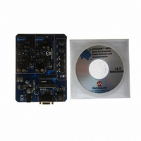
DM300023
Description
KIT DEMO DSPICDEM SMPS BUCK
Manufacturer
Microchip Technology
Series
dsPIC™r
Datasheets
1.AC164335.pdf
(286 pages)
2.DM300023.pdf
(22 pages)
3.DM300023.pdf
(18 pages)
4.DM300023.pdf
(50 pages)
5.DM300023.pdf
(16 pages)
Specifications of DM300023
Main Purpose
DC/DC, Step Down
Outputs And Type
2, Non-Isolated
Voltage - Input
7 ~ 15V
Regulator Topology
Buck
Board Type
Fully Populated
Utilized Ic / Part
dsPIC30F2020
Processor To Be Evaluated
dsPIC30F202x/1010
Interface Type
RS-232
Lead Free Status / RoHS Status
Lead free / RoHS Compliant
Current - Output
-
Voltage - Output
-
Power - Output
-
Frequency - Switching
-
Lead Free Status / Rohs Status
Lead free / RoHS Compliant
Available stocks
Company
Part Number
Manufacturer
Quantity
Price
Company:

Part Number:
DM300023
Manufacturer:
Microchip Technology
Quantity:
135
Company:
Part Number:
DM300023
Manufacturer:
MICROCHIP
Quantity:
12 000


32. Module: MCLR Pin
EXAMPLE 1:
© 2008 Microchip Technology Inc.
; This function performs a clock-switch from FRC to FRC+PLL. All other oscillator
; settings remain unchanged.
; Filename: ClockSwitch.s
_ClockSwitch:
A brown-out event occurs when V
the minimum operating voltage for the device but
not all the way down to V
SMPS device is running with the PLL enabled and
a brown-out event occurs, the device may stop
running and the MCLR pin will not reset the device.
If this occurs, the device can only be reset by
cycling power to the V
It is recommended that an external Brown-out
Reset (BOR) circuit be used to hold the device in
reset during a brown-out event, to overcome this
problem. The external BOR circuit will use the
MCLR pin to hold the device in reset. The following
work around, in combination with the external BOR
circuit, will ensure that the device is cleanly reset
after a brown-out event occurs.
Work around
The dsPIC DSC SMPS device must be powered
up with the PLL disabled, the Fail-Safe Clock
Monitor enabled and Clock Switching enabled.
The PLL should be enabled in software via a clock
switch after the device is reset (refer to Section
29. “Oscillator” in the “dsPIC30F Family
Reference Manual” (DS70268) for details on clock
switching). This ensures that the MCLR pin is
functional and that the device can be reset by an
external BOR circuit (see Figure 1).
mov
mov
mov
mov
mov.b
mov.b
mov.b
mov
mov
mov
mov
mov.b
mov.b
mov.b
return
#OSCCON+1,w4
#0x0078, w0
#0x009A, w1
#0x0001, w2
w0, [w4]
w1, [w4]
w2, [w4]
#OSCCON,w4
#0x0046, w0
#0x0057, w1
#0x0001, w2
w0, [w4]
w1, [w4]
w2, [w4]
CLOCK SWITCHING EXAMPLE
DD
SS
pins.
. When the dsPIC DSC
; Get address of high OSCCON byte
; 1st password for high byte access to OSCCON
; 2nd password for low byte access to OSCCON
; NOSC value for FRC+PLL
; Write 1st password
; Write 2nd password
; Write NOSC value
; Get address of low OSCCON byte
; 1st password for high byte access to OSCCON
; 2nd password for low byte access to OSCCON
; Set OSWEN bit
; Write 1st password
; Write 2nd password
; Write OSWEN bit
DD
drops below
FIGURE 1:
*Any commercially available BOR circuit
can be used in this configuration. Refer to
the BOR circuit manufacturer’s data sheet
for exact circuit configuration.
dsPIC30F1010/202X
Use one of the following methods to achieve the
work around.
Method 1: Insert the code shown in Example 1 at
the start of the program.
Method 2: Call the code shown in Example 1 in
the beginning of code execution by including the
ClockSwitch.s file in the project and adding the
following code:
• For assembly programming, add the following
• For C programming, add the following
+5V
instruction at the beginning of the program:
instruction at the beginning of the program:
.global __reset
…
…
__reset:
rcall ClockSwitch
…
…
int main(void)
{
}
External
Circuit
BOR
U2*
ClockSwitch;
…
…
R*
U1
DS80319D-page 11
MCLR
V
SS
+5V
Related parts for DM300023
Image
Part Number
Description
Manufacturer
Datasheet
Request
R

Part Number:
Description:
Manufacturer:
Microchip Technology Inc.
Datasheet:
Part Number:
Description:
Manufacturer:
Microchip Technology Inc.
Datasheet:
Part Number:
Description:
Manufacturer:
Microchip Technology Inc.
Datasheet:
Part Number:
Description:
Manufacturer:
Microchip Technology Inc.
Datasheet:
Part Number:
Description:
Manufacturer:
Microchip Technology Inc.
Datasheet:
Part Number:
Description:
Manufacturer:
Microchip Technology Inc.
Datasheet:
Part Number:
Description:
Manufacturer:
Microchip Technology Inc.
Datasheet:
Part Number:
Description:
Manufacturer:
Microchip Technology Inc.
Datasheet: