DAK-93 Power Integrations, DAK-93 Datasheet
DAK-93
Specifications of DAK-93


Related parts for DAK-93


DAK-93 Summary of contents
Page 1
... Engineering Prototype Report for EP-93 – 32 W/81 W Peak Supply Using Title PeakSwitch 90-265 VAC Input 1.07 A (continuous), Specification 2 A (100 ms), 2.7 A (50 ms) Output Application Printers, DVRs, Audio, General Purpose Author Power Integrations Applications Department Document EPR-93 Number Date 22-Jun-2006 Revision 1.4 Summary and Features • ...
Page 2
... The products and applications illustrated herein (including circuits external to the products and transformer construction) may be covered by one or more U.S. and foreign patents or potentially by pending U.S. and foreign patent applications assigned to Power Integrations. A complete list of Power Integrations’ patents may be found at www.powerint.com. ...
Page 3
... Measurement Results.................................................................................31 13 Output Over-current Shutdown/Restart .................................................................32 14 Line Surge.............................................................................................................33 15 Conducted EMI .....................................................................................................34 16 Appendix ...............................................................................................................36 16.1 Heat Sink Drawing .............................................................................................36 17 Revision History ....................................................................................................37 Page EP-93 – 1.07 A, 2.7 A (peak), Universal Input Supply Tel: +1 408 414 9200 Fax: +1 408 414 9201 Power Integrations www.powerint.com ...
Page 4
... Although this board is designed to satisfy safety isolation requirements, the engineering prototype has not been agency approved. Therefore, all testing should be performed using an isolation transformer to provide the AC input to the prototype board. Power Integrations Tel: +1 408 414 9200 Fax: +1 408 414 9201 www.powerint.com ...
Page 5
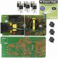
... The document contains the power supply specification, schematic, bill of materials, transformer documentation, printed circuit layout, and performance data. Figure 1 – EP-93 Populated Circuit Board Photograph. Page EP-93 – 1.07 A, 2.7 A (peak), Universal Input Supply Tel: +1 408 414 9200 Fax: +1 408 414 9201 Power Integrations www.powerint.com ...
Page 6
... Continuous Output Power Peak Output Power Efficiency Full Load Required average efficiency at 25, 50, 75 and 100 % of P OUT Environmental Conducted EMI Safety Surge Surge Ambient Temperature Power Integrations Tel: +1 408 414 9200 Fax: +1 408 414 9201 www.powerint.com Symbol Min Typ Max V 90 265 ...
Page 7
... Schematic Page EP-93 – 1.07 A, 2.7 A (peak), Universal Input Supply Figure 2 – EP-93 Schematic. Tel: +1 408 414 9200 Fax: +1 408 414 9201 Power Integrations www.powerint.com ...
Page 8
... Diode D7, C6, C8, and R7 provide bias power and decoupling to U1. Diode D6, C5, R3, R4, and VR1 clamp the U1 drain voltage to safe levels. Use of a moderately slow diode (t RR Power Integrations Tel: +1 408 414 9200 Fax: +1 408 414 9201 www.powerint.com ≤ 500 ns) for D6 increases power supply efficiency. ...
Page 9
... The shutdown condition can be reset by briefly removing AC power for ~3 seconds (maximum), the time required for C7 to discharge and the current into the EN/UV pin to fall below 25 µA. Page EP-93 – 1.07 A, 2.7 A (peak), Universal Input Supply Tel: +1 408 414 9200 Fax: +1 408 414 9201 Power Integrations www.powerint.com ...
Page 10
... EP-93 – 1.07 A, 2.7 A (peak), Universal Input Supply 5 PCB Layout Power Integrations Tel: +1 408 414 9200 Fax: +1 408 414 9201 www.powerint.com Figure 3 – EP-93 Printed Circuit Layout. 22-Jun-2006 Page ...
Page 11
... Vishay FR106 Diodes Inc. 1N4148 Vishay STPS3150RL ST UF4003 Vishay 3,821,315,0410 Wickman Custom Clark Precision Sheetmetal 161-R301SN13 Kobiconn 26-48-1021 Molex N/A N/A 298 Alpha 298 Alpha ELF15N010A Panasonic Custom 2N3906 Vishay FS0202DA Fagor CFR-25JB-1M3 Yageo CFR-50JB-10K Yageo CFR-50JB-22R Yageo Power Integrations www.powerint.com ...
Page 12
... Silicone Heat Sink Compound 59 1 C4, RT1, L2 Silicone Adhesive, Non-corrosive (REF) Note: (REF) indicates mechanical items associated with the referenced component(s) but that are not shown on the schematic. Power Integrations Tel: +1 408 414 9200 Fax: +1 408 414 9201 www.powerint.com 22-Jun-2006 CFR-25JB-2M2 Yageo CFR-25JB-2M4 ...
Page 13
... X 29 AWG WDG #1 20T AWG WDG #2 5T Figure 4 – Transformer Electrical Diagram. 1 Second, from Pins 1-5 to Pins 6-10 Tel: +1 408 414 9200 Fax: +1 408 414 9201 9,10 7,8 3000 VAC (Min.) 132 µH, ±10% 2 MHz (Min.) 5.5 µH (Max.) Power Integrations www.powerint.com ...
Page 14
... Tape, 3M #1298 or Equivalent 10.8 mm Wide [6] Varnish 7.4 Transformer Build Diagram Pins Side 7,8 Tape 9, Power Integrations Tel: +1 408 414 9200 Fax: +1 408 414 9201 www.powerint.com Description nH/T L Figure 5 – Transformer Build Diagram. 22-Jun-2006 ½ Primary Shield Secondary Bias ½ Primary Page ...
Page 15
... Pin 1. Finish Wrap Use three layers of item [5] for finish wrap. Final Assembly Assemble and secure core halves. Dip Varnish (item [6]). Page EP-93 – 1.07 A, 2.7 A (peak), Universal Input Supply Tel: +1 408 414 9200 Fax: +1 408 414 9201 Power Integrations www.powerint.com ...
Page 16
... KP (TRANSIENT) ENTER UVLO VARIABLES V_UV_TARGET V_UV_ACTUAL RUV_IDEAL RUV_ACTUAL BIAS WINDING VARIABLES VB NB PIVB Power Integrations Tel: +1 408 414 9200 Fax: +1 408 414 9201 www.powerint.com OUTPUT UNIT ACDC_PeakSwitch_031006_Rev1-1.xls; PeakSwitch Continuous/Discontinuous Flyback Transformer Design Spreadsheet Volts Minimum AC Input Voltage Volts Maximum AC Input Voltage ...
Page 17
... Maximum Primary Wire Diameter including insulation Estimated Total Insulation Thickness (= 2 * film thickness) Bare conductor diameter Primary Wire Gauge (Rounded to next smaller standard AWG value) Bare conductor effective area in circular mils Primary Winding Current Capacity Amp (100 < CMA < 500) Power Integrations www.powerint.com ...
Page 18
... Lumped parameters ISP ISRMS IRIPPLE CMS AWGS VOLTAGE STRESS PARAMETERS VDRAIN PIVS Power Integrations Tel: +1 408 414 9200 Fax: +1 408 414 9201 www.powerint.com 10.06 Amps Peak Secondary Current 5.44 Amps Secondary RMS Current 4.72 Amps Output Capacitor RMS Ripple Current 1089 Cmils ...
Page 19
... Load 50% Load 25% Load 120 140 160 180 200 AC Input Voltage Minimum Efficiency in Active Mode of Operation 0.49 × 0.09 × 0.49 [ln = natural log] O 0.84 Tel: +1 408 414 9200 Fax: +1 408 414 9201 220 240 260 280 Minimum active mode Power Integrations www.powerint.com ...
Page 20
... CEC/Energy Star standard. More states within the USA and other countries are adopting this standard. For the latest up to date information please visit the PI Green Room: http://www.powerint.com/greenroom/regulations.htm Power Integrations Tel: +1 408 414 9200 Fax: +1 408 414 9201 www.powerint.com Efficiency (%) Percent of ...
Page 21
... EP-93 – 1.07 A, 2.7 A (peak), Universal Input Supply 120 140 160 180 200 AC Input Voltage 120 140 160 180 200 AC Input Voltage Tel: +1 408 414 9200 Fax: +1 408 414 9201 220 240 260 280 Pin = 1W Pin = 3W 220 240 260 280 and Power Integrations www.powerint.com ...
Page 22
... Figure 10 – Line Regulation, Room Temperature, Full Load. (32 W). Power Integrations Tel: +1 408 414 9200 Fax: +1 408 414 9201 www.powerint.com 0.2 0.3 0.4 0.5 0.6 0.7 Output Load (A) 120 140 160 180 ...
Page 23
... EP-93 – 1.07 A, 2.7 A (peak), Universal Input Supply Temperature Item (°C) 85 VAC Ambient 25.2 D8 (Output Rectifier) 65.8 C12 (Output Capacitor) 47.0 U1 (PeakSwitch) 70.0 T1 (Transformer) 58.0 L1 (Common Mode Choke) 47.0 C4 (Bulk Capacitor) 34.7 Tel: +1 408 414 9200 Fax: +1 408 414 9201 Power Integrations www.powerint.com ...
Page 24
... Upper 100 V / div. DRAIN , 0 µs / div. Lower: I DRAIN 11.2 Output Voltage Start-up Profile Figure 13 – Start-Up Profile, 90 VAC div. Power Integrations Tel: +1 408 414 9200 Fax: +1 408 414 9201 www.powerint.com – Figure 12 265 VAC, Full Load. Upper 200 V / div. DRAIN Lower 0 µ ...
Page 25
... EP-93 – 1.07 A, 2.7 A (peak), Universal Input Supply Figure 16 – 265 VAC Input Load. Upper: V Lower: I Figure 18 – Transient Response, 265 VAC Load Step. Upper: Output Voltage, 1 V/div. Lower: Load Current ms/div. Tel: +1 408 414 9200 Fax: +1 408 414 9201 , 200 div. DRAIN , div. DRAIN Power Integrations www.powerint.com ...
Page 26
... Holdup Time All measurements taken output load. Figure 19 – Holdup Time, 90 VAC. Top Trace: Output Voltage, 20 V/div. Middle Trace: Output Current, 1 A/div. Bottom Trace: AC Input Current ms/div. Power Integrations Tel: +1 408 414 9200 Fax: +1 408 414 9201 www.powerint.com 22-Jun-2006 Page ...
Page 27
... Bottom Trace: AC Input Voltage, 100 V, 20 ms/div. Figure 23 – Half-Cycle Dropout, 240 VAC, 50 Hz. Top Trace: Output Voltage, 20 V/div. Middle Trace: Output Current, 2 A/div. Bottom Trace: AC Input Voltage, 200 V, 20 ms/div. Tel: +1 408 414 9200 Fax: +1 408 414 9201 Power Integrations www.powerint.com ...
Page 28
... Hz. Top Trace: Output Voltage, 20 V/div. Middle Trace: Output Current, 2 A/div. Bottom Trace: AC Input Voltage, 100 V, 200 ms/div. Power Integrations Tel: +1 408 414 9200 Fax: +1 408 414 9201 www.powerint.com Figure 25 – Full Cycle Dropout, 240 VAC, 50 Hz. Top Trace: Output Voltage, 20 V/div. ...
Page 29
... Top Trace: Output Voltage, 10 V/div. Bottom Trace: AC Input Voltage, 500 V, 100 ms/div. Page EP-93 – 1.07 A, 2.7 A (peak), Universal Input Supply Figure 29 – Peak Drain Voltage During 300 VAC Line Swell, 100 V, 2 µs/div. Tel: +1 408 414 9200 Fax: +1 408 414 9201 Power Integrations www.powerint.com ...
Page 30
... Figure 30 – Oscilloscope Probe Prepared for Ripple Measurement (End Cap and Ground Lead Removed). Figure 31 – Oscilloscope Probe with Probe Master 5125BA BNC Adapter (Modified with Wires for Probe Ground for Ripple Measurement, and Two Parallel Decoupling Capacitors Added). Power Integrations Tel: +1 408 414 9200 Fax: +1 408 414 9201 www.powerint.com ...
Page 31
... Figure 32 – Output Ripple, 90 VAC, 60 Hz, Full Load. 200 mV div. Page EP-93 – 1.07 A, 2.7 A (peak), Universal Input Supply Figure 33 – Output Ripple, 265 VAC, 50 Hz, Full Load. 200 mV div. Tel: +1 408 414 9200 Fax: +1 408 414 9201 Power Integrations www.powerint.com ...
Page 32
... Current Shutdown and AC Input Recycle, 115 VAC. Top Trace: Output Voltage, 20 V/div. Middle Trace: Output Current, 1 A/div. Bottom Trace: AC Input Voltage, 100 V, 500 ms/div. Power Integrations Tel: +1 408 414 9200 Fax: +1 408 414 9201 www.powerint.com Figure 35 – Supply Shutdown After Output Load Step from 1 ...
Page 33
... Injection Injection Test Result Location Phase (°) (Pass/Fail Pass Pass Pass Pass 270 Pass 270 Pass Pass GND Pass GND Pass GND Pass GND 270 Pass GND 270 Pass GND Tel: +1 408 414 9200 Fax: +1 408 414 9201 Power Integrations www.powerint.com ...
Page 34
... LISN via a 2-meter IEC line cord arranged in a serpentine pattern. The power supply secondary return was hard-wired to the LISN ground using a 1-meter cable. – Figure 37 Conducted EMI, Maximum Steady State Load, 115 VAC, 60 Hz, and EN55022 B Limits. Power Integrations Tel: +1 408 414 9200 Fax: +1 408 414 9201 www.powerint.com 22-Jun-2006 Page ...
Page 35
... Figure 38 – Conducted EMI, Maximum Steady State Load, 230 VAC, 60 Hz, and EN55022 B Limits. Page EP-93 – 1.07 A, 2.7 A (peak), Universal Input Supply Tel: +1 408 414 9200 Fax: +1 408 414 9201 Power Integrations www.powerint.com ...
Page 36
... EP-93 – 1.07 A, 2.7 A (peak), Universal Input Supply 16 Appendix 16.1 Heat Sink Drawing Power Integrations Tel: +1 408 414 9200 Fax: +1 408 414 9201 www.powerint.com 22-Jun-2006 Page ...
Page 37
... Description & changes 1.0 First Release 1.1 Fix board picture and add transformer suppliers 1.2 Format for printing 1.3 Updated PeakSwitch symbol in Figure 2 1.4 Revised ground connection on the circuit diagram in Figure 2 Tel: +1 408 414 9200 Fax: +1 408 414 9201 Power Integrations www.powerint.com ...
Page 38
... EP-93 – 1.07 A, 2.7 A (peak), Universal Input Supply Power Integrations Tel: +1 408 414 9200 Fax: +1 408 414 9201 www.powerint.com Notes 22-Jun-2006 Page ...
Page 39
... Page EP-93 – 1.07 A, 2.7 A (peak), Universal Input Supply Notes Tel: +1 408 414 9200 Fax: +1 408 414 9201 Power Integrations www.powerint.com ...
Page 40
... EP-93 – 1.07 A, 2.7 A (peak), Universal Input Supply For the latest updates, visit our website: www.powerint.com Power Integrations reserves the right to make changes to its products at any time to improve reliability or manufacturability. Power Integrations does not assume any liability arising from the use of any device or circuit described herein. POWER INTEGRATIONS ...