DAK-93 Power Integrations, DAK-93 Datasheet - Page 3
DAK-93
Manufacturer Part Number
DAK-93
Description
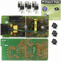
KIT DESIGN ACC PEAKSWITCH FAMILY
Manufacturer
Power Integrations
Series
PeakSwitch®r
Specifications of DAK-93
Main Purpose
AC/DC, Primary Side
Outputs And Type
1, Isolated
Power - Output
32W
Voltage - Output
30V
Current - Output
1.07A
Voltage - Input
90 ~ 265VAC
Regulator Topology
Flyback
Board Type
Bare (Unpopulated) and Fully Populated
Utilized Ic / Part
PKS604, PKS605, PKS606
Lead Free Status / RoHS Status
Lead free / RoHS Compliant
Frequency - Switching
-
Lead Free Status / Rohs Status
Lead free / RoHS Compliant
Other names
596-1126


22-Jun-2006
Table Of Contents
1
2
3
4
5
6
7
8
9
10
11
12
13
14
15
16
17
Page 3 of 40
4.1
4.2
4.3
4.4
4.5
7.1
7.2
7.3
7.4
7.5
9.1
9.2
9.3
9.4
11.1
11.2
11.3
11.4
11.5
11.6
16.1
Introduction .................................................................................................................5
Power Supply Specification ........................................................................................6
Schematic ...................................................................................................................7
Circuit Description.......................................................................................................8
PCB Layout...............................................................................................................10
Bill Of Materials.........................................................................................................11
Transformer Specification .........................................................................................13
Transformer Spreadsheet .........................................................................................16
Performance Data.....................................................................................................19
9.1.1
9.4.1
9.4.2
12.1.1
12.1.2
Thermal Performance............................................................................................23
Waveforms ............................................................................................................24
Output Ripple Measurements................................................................................30
Output Over-current Shutdown/Restart .................................................................32
Line Surge.............................................................................................................33
Conducted EMI .....................................................................................................34
Appendix ...............................................................................................................36
Revision History ....................................................................................................37
Input EMI Filtering................................................................................................8
PeakSwitch Primary.............................................................................................8
Output Rectification and Filtering.........................................................................9
Output Feedback .................................................................................................9
Output Protection.................................................................................................9
Electrical Diagram..............................................................................................13
Electrical Specifications .....................................................................................13
Materials ............................................................................................................14
Transformer Build Diagram................................................................................14
Transformer Construction ..................................................................................15
Efficiency ...........................................................................................................19
No-load Input Power ..........................................................................................21
Available Standby Output Power .......................................................................21
Regulation .........................................................................................................22
Drain Voltage and Current, Normal Operation...................................................24
Output Voltage Start-up Profile ..........................................................................24
Drain Voltage and Current Start-up Profile ........................................................25
Load Transient Response (1 A to 2 A Load Step) .............................................25
Holdup Time ......................................................................................................26
AC Line Disturbance..........................................................................................27
Heat Sink Drawing .............................................................................................36
Active Mode CEC Measurement Data........................................................19
Load Regulation .........................................................................................22
Line Regulation...........................................................................................22
Ripple Measurement Technique.................................................................30
Measurement Results.................................................................................31
EP-93 – 30 V, 1.07 A, 2.7 A (peak), Universal Input Supply
Tel: +1 408 414 9200 Fax: +1 408 414 9201
Power Integrations
www.powerint.com
Related parts for DAK-93
Image
Part Number
Description
Manufacturer
Datasheet
Request
R

Part Number:
Description:
KIT DESIGN ACCELERATOR MODEM
Manufacturer:
Power Integrations
Datasheet:

Part Number:
Description:
KIT DESIGN ACCELERATOR SET TOP
Manufacturer:
Power Integrations
Datasheet:

Part Number:
Description:
KIT REF DES DPA 6.6W DC-DC CONV
Manufacturer:
Power Integrations
Datasheet:

Part Number:
Description:
KIT DESIGN ACCELERATOR POE CONV
Manufacturer:
Power Integrations
Datasheet:

Part Number:
Description:
DESIGN ACCELERATOR KIT XT SWITCH
Manufacturer:
Power Integrations
Datasheet:

Part Number:
Description:
DESIGN ACCELERATOR KIT LP SWITCH
Manufacturer:
Power Integrations
Datasheet:

Part Number:
Description:
KIT DESIGN ACCELERATOR ADAPTER
Manufacturer:
Power Integrations
Datasheet:

Part Number:
Description:
KIT DESIGN ACCELERATOR ADAPTER
Manufacturer:
Power Integrations
Datasheet:

Part Number:
Description:
KIT DESIGN ACCELERATOR DC-DC
Manufacturer:
Power Integrations
Datasheet:

Part Number:
Description:
KIT DESIGN ACCELERATOR DPA SW
Manufacturer:
Power Integrations
Datasheet: