DAK-93 Power Integrations, DAK-93 Datasheet - Page 17
DAK-93
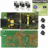
Manufacturer Part Number
DAK-93
Description
KIT DESIGN ACC PEAKSWITCH FAMILY
Manufacturer
Power Integrations
Series
PeakSwitch®r
Specifications of DAK-93
Main Purpose
AC/DC, Primary Side
Outputs And Type
1, Isolated
Power - Output
32W
Voltage - Output
30V
Current - Output
1.07A
Voltage - Input
90 ~ 265VAC
Regulator Topology
Flyback
Board Type
Bare (Unpopulated) and Fully Populated
Utilized Ic / Part
PKS604, PKS605, PKS606
Lead Free Status / RoHS Status
Lead free / RoHS Compliant
Frequency - Switching
-
Lead Free Status / Rohs Status
Lead free / RoHS Compliant
Other names
596-1126


22-Jun-2006
ENTER TRANSFORMER CORE/CONSTRUCTION VARIABLES
Core Type
Core
Bobbin
AE
LE
AL
BW
M
L
NS
DC INPUT VOLTAGE PARAMETERS
VMIN
VMAX
CURRENT WAVEFORM SHAPE PARAMETERS
DMAX
IAVG
IP
IR
IRMS
TRANSFORMER PRIMARY DESIGN PARAMETERS
LP
LP_TOLERANCE
NP
ALG
Target BM
BM
BAC
ur
LG
BWE
OD
INS
DIA
AWG
CM
CMA
Page 17 of 40
EE25
10.00
10
EP-93 – 30 V, 1.07 A, 2.7 A (peak), Universal Input Supply
ON-Time
Extension
EE25
EE25_BOBBIN
EE25
Tel: +1 408 414 9200 Fax: +1 408 414 9201
0.404 cm^2
10.20 mm
1420 nH/T^2
3000 Gauss
2523 Gauss
2053
7.34 cm
0.00 mm
0.62
1.34 Amps
2.60 Amps
1.31 Amps
1.80 Amps
0.54 mm
30.6 mm
0.79 mm
0.08 mm
0.71 mm
375 Volts
132 uHenries Typical Primary Inductance. +/- 10% to
635 Gauss
645 Cmils
358 Cmils/
10
81 Volts
10 %
39
88 nH/T^2
22 AWG
3
P/N:
P/N:
Amp
User Selected Core Size(Verify
acceptable thermal rise under continuous
load conditions)
PC40EE25-Z
EE25_BOBBIN
Core Effective Cross Sectional Area
Core Effective Path Length
Ungapped Core Effective Inductance
Bobbin Physical Winding Width
Safety Margin Width (Half the Primary to
Secondary Creepage Distance)
Number of Primary Layers
Number of Secondary Turns
Minimum DC Input Voltage
Maximum DC Input Voltage
!!! Info. ON-Time Extension feature
invoked. Verify this design for acceptable
electrical and thermal performance on the
bench
Average Primary Current
Minimum Peak Primary Current
Primary Ripple Current
Primary RMS Current
ensure a minimum primary inductance of
119 uH
Primary inductance tolerance
Primary Winding Number of Turns
Gapped Core Effective Inductance
Target Peak Flux Density at Maximum
Current Limit
Calculated Maximum Operating Flux
Density, BM < 3000 is recommended
AC Flux Density for Core Loss Curves
(0.5 X Peak to Peak)
Relative Permeability of Ungapped Core
Gap Length (Lg > 0.1 mm)
Effective Bobbin Width
Maximum Primary Wire Diameter
including insulation
Estimated Total Insulation Thickness
(= 2 * film thickness)
Bare conductor diameter
Primary Wire Gauge (Rounded to next
smaller standard AWG value)
Bare conductor effective area in circular
mils
Primary Winding Current Capacity
(100 < CMA < 500)
Power Integrations
www.powerint.com
Related parts for DAK-93
Image
Part Number
Description
Manufacturer
Datasheet
Request
R

Part Number:
Description:
KIT DESIGN ACCELERATOR MODEM
Manufacturer:
Power Integrations
Datasheet:

Part Number:
Description:
KIT DESIGN ACCELERATOR SET TOP
Manufacturer:
Power Integrations
Datasheet:

Part Number:
Description:
KIT REF DES DPA 6.6W DC-DC CONV
Manufacturer:
Power Integrations
Datasheet:

Part Number:
Description:
KIT DESIGN ACCELERATOR POE CONV
Manufacturer:
Power Integrations
Datasheet:

Part Number:
Description:
DESIGN ACCELERATOR KIT XT SWITCH
Manufacturer:
Power Integrations
Datasheet:

Part Number:
Description:
DESIGN ACCELERATOR KIT LP SWITCH
Manufacturer:
Power Integrations
Datasheet:

Part Number:
Description:
KIT DESIGN ACCELERATOR ADAPTER
Manufacturer:
Power Integrations
Datasheet:

Part Number:
Description:
KIT DESIGN ACCELERATOR ADAPTER
Manufacturer:
Power Integrations
Datasheet:

Part Number:
Description:
KIT DESIGN ACCELERATOR DC-DC
Manufacturer:
Power Integrations
Datasheet:

Part Number:
Description:
KIT DESIGN ACCELERATOR DPA SW
Manufacturer:
Power Integrations
Datasheet: