EVLVIP27H-12SB STMicroelectronics, EVLVIP27H-12SB Datasheet - Page 18
EVLVIP27H-12SB
Manufacturer Part Number
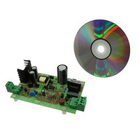
EVLVIP27H-12SB
Description
BOARD EVAL FOR VIPER27HD
Manufacturer
STMicroelectronics
Series
VIPer™ plusr
Datasheet
1.VIPER27LD.pdf
(31 pages)
Specifications of EVLVIP27H-12SB
Main Purpose
AC/DC, Primary Side
Power - Output
24W
Voltage - Output
800V
Current - Output
2.5mA
Voltage - Input
8.5 ~ 23.5 V
Regulator Topology
Flyback
Frequency - Switching
115kHz
Board Type
Fully Populated
Utilized Ic / Part
VIPer27
Lead Free Status / RoHS Status
Lead free by exemption / RoHS compliant by exemption
Outputs And Type
-
Lead Free Status / Rohs Status
Lead free / RoHS Compliant
Other names
497-10166


Operation descriptions
7.7
7.8
18/31
Current mode conversion with adjustable current limit set
point
The device is a current mode converter: the drain current is sensed and converted in voltage
that is applied to the non inverting pin of the PWM comparator. This voltage is compared
with the one on the feed-back pin through a voltage divider on cycle by cycle basis.
The
the electrical specification, by the R
page 11
The CONT pin has a minimum current sunk needed to activate the I
R
Table 8 on page 7
Overvoltage protection (OVP)
The VIPER27 has integrated the logic for the monitor of the output voltage using as input
signal the voltage V
the voltage from the auxiliary winding tracks the output voltage, through the turn ratio
The CONT pin has to be connected to the auxiliary winding through the diode D
resistors R
the voltage V
on page 7
the auto-restart mode.
In order to bypass the noise immediately after the turn off of the power MOSFET, the voltage
V
the
digital signal and increments the internal counter. The same counter is reset every time the
signal OVP is not triggered in one oscillator cycle.
Referring to the
Equation 2
Equation 3
N
--------------
N
CONT
LIM
AUX
SEC
Figure 26 on page 19
VIPER27
or with high R
is sampled inside a short window after the time T
.
) the overvoltage protection will stop the power MOSFET and the converter enters
OVP
CONT
has a default current limit value, I
and R
Figure 21
).
exceeds, four consecutive times, the reference voltage V
LIM
CONT
LIM
(i.e. 100 kΩ) the current limit is fixed to the default value (see I
as shows the
k
during the OFF time of the power MOSFET. This is the time when
. The sampled signal, if higher than V
, the resistors divider ratio k
OVP
=
Doc ID 15133 Rev 5
-------------------------------------------------------------------------------------------------- -
N
--------------
N
AUX
SEC
LIM
k
OVP
⋅
Figure 27 on page 20
resistor connected to the CONT see
(
V
=
OUTOVP
--------------------------------- -
R
LIM
Dlim
V
R
OVP
+
LIM
+
, that the designer can adjust according
R
V
OVP
DSEC
OVP
STROBE
) V
will be given by:
–
When, during the OFF time,
DAUX
OVP
, see
, trigger the internal OVP
Dlim
Table 8 on page 7
adjustment: without
OVP
Figure 16 on
(see
OVP
VIPER27
and the
Table 8
Dlim
and
,
Related parts for EVLVIP27H-12SB
Image
Part Number
Description
Manufacturer
Datasheet
Request
R

Part Number:
Description:
EVAL BOARD FOR VIPER27
Manufacturer:
STMicroelectronics
Datasheet:

Part Number:
Description:
STMicroelectronics [RIPPLE-CARRY BINARY COUNTER/DIVIDERS]
Manufacturer:
STMicroelectronics
Datasheet:
Part Number:
Description:
STMicroelectronics [LIQUID-CRYSTAL DISPLAY DRIVERS]
Manufacturer:
STMicroelectronics
Datasheet:

Part Number:
Description:
BOARD EVAL FOR MEMS SENSORS
Manufacturer:
STMicroelectronics
Datasheet:
Part Number:
Description:
NPN TRANSISTOR POWER MODULE
Manufacturer:
STMicroelectronics
Datasheet:
Part Number:
Description:
TURBOSWITCH ULTRA-FAST HIGH VOLTAGE DIODE
Manufacturer:
STMicroelectronics
Datasheet:
Part Number:
Description:
Manufacturer:
STMicroelectronics
Datasheet:
Part Number:
Description:
DIODE / SCR MODULE
Manufacturer:
STMicroelectronics
Datasheet:
Part Number:
Description:
DIODE / SCR MODULE
Manufacturer:
STMicroelectronics
Datasheet:
Part Number:
Description:
Search -----> STE16N100
Manufacturer:
STMicroelectronics
Datasheet:
Part Number:
Description:
Search ---> STE53NA50
Manufacturer:
STMicroelectronics
Datasheet:
Part Number:
Description:
NPN Transistor Power Module
Manufacturer:
STMicroelectronics
Datasheet: