STEVAL-ISA050V1 STMicroelectronics, STEVAL-ISA050V1 Datasheet - Page 37
STEVAL-ISA050V1
Manufacturer Part Number
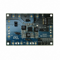
STEVAL-ISA050V1
Description
KIT EVAL PM6641 CHIPSET/DDR2/3
Manufacturer
STMicroelectronics
Type
DC/DC Switching Converters, Regulators & Controllersr
Specifications of STEVAL-ISA050V1
Main Purpose
Special Purpose DC/DC, DDR Memory Supply
Outputs And Type
4, Non-Isolated
Power - Output
14.7W
Voltage - Output
1.05V, 1.5V, 1.8V, 0.9V
Current - Output
4A, 2.8A, 2.5A, 2A
Voltage - Input
2.7 ~ 5.5V
Regulator Topology
Buck
Frequency - Switching
750kHz
Board Type
Fully Populated
Utilized Ic / Part
PM6641
Input Voltage
2.7 V to 5.5 V
Product
Power Management Modules
Silicon Manufacturer
ST Micro
Silicon Core Number
PM6641
Kit Application Type
Power Management - Voltage Regulator
Application Sub Type
Monolithic Voltage Regulator
Kit Contents
Board
Lead Free Status / RoHS Status
Lead free / RoHS Compliant
For Use With/related Products
PM6641
Other names
497-8425
Available stocks
Company
Part Number
Manufacturer
Quantity
Price
Company:

Part Number:
STEVAL-ISA050V1
Manufacturer:
STMicroelectronics
Quantity:
1


PM6641
8.3
The losses due to the input capacitor are thus maximized when the duty-cycle is 0.5:
Equation 18
The input capacitor should be selected with a RMS rated current higher than I
Tantalum capacitors are good in term of low ESR and small size, but they occasionally can
burn out if subjected to very high current during operation. Multi-Layers-Ceramic-Capacitors
(MLCC) have usually a higher RMS current rating with smaller size and very low ESR.
When only one common input capacitor is chosen for the application, instead of one
dedicated capacitor for each regulator (close to each input power supply pins), the total
input current can be quite different from the arithmetic sum of the buck regulators RMS input
currents, if phase management is allowed (see
page 30
Output capacitor selection
Using tantalum or electrolytic capacitors, the selection is made referring to ESR and voltage
rating rather than by a specific capacitance value.
The output capacitor has to satisfy the output voltage ripple requirements. At a given
switching frequency, small inductor values are useful to reduce the size of the choke but
increase the inductor current ripple. Thus, to reduce the output voltage ripple a low ESR
capacitor is required:
Equation 19
where V
The zero introduced by the output capacitor ESR must be higher than the switching
frequency or must be compensated (see
page 24
Equation 20
In order to minimize the output voltage ripple, ceramic capacitors are suggested.
RIPPLE
section for details).
section for details):
is the maximum tolerable ripple voltage.
P
loss
=
ESR
Cin
Doc ID 13510 Rev 3
f
⋅
SW
I
2
CinRMS
ESR
>
f
Z
Chapter 7.3: SW regulators control loop on
=
≤
,
MAX
------------------------------------------- -
2π ESR C
V
RIPPLE
Δ
⋅
=
I
Chapter 7.9: Phase management on
, L
ESR
MAX
1
,
MAX
⋅
Cin
OUT
⋅
(
0
5 .
⋅
I
LOAD
,
Components selection
MAX
)
2
CinRMS,MAX
37/47
.
Related parts for STEVAL-ISA050V1
Image
Part Number
Description
Manufacturer
Datasheet
Request
R

Part Number:
Description:
BOARD RGB CTR ST7,STP08C596MTR
Manufacturer:
STMicroelectronics
Datasheet:

Part Number:
Description:
Power Management IC Development Tools Full Speed USB to RS232 Bridge Demo
Manufacturer:
STMicroelectronics
Datasheet:
Part Number:
Description:
Power Management IC Development Tools 2.5W solar eval BRD USB SPV1040 LD39050
Manufacturer:
STMicroelectronics
Datasheet:

Part Number:
Description:
BOARD EVAL FOR MEMS SENSORS
Manufacturer:
STMicroelectronics
Datasheet:

Part Number:
Description:
KIT DEV STARTER ST10F276Z5
Manufacturer:
STMicroelectronics
Datasheet:

Part Number:
Description:
BOARD EVAL HDMI $ VIDEO SWITCH
Manufacturer:
STMicroelectronics
Datasheet:

Part Number:
Description:
BOARD DEMO ACCELEROMETER DIL24
Manufacturer:
STMicroelectronics
Datasheet:

Part Number:
Description:
BOARD STLM75/STDS75/ST72F651
Manufacturer:
STMicroelectronics
Datasheet:

Part Number:
Description:
EVAL BOARD 3AXIS MEMS ACCELLRMTR
Manufacturer:
STMicroelectronics
Datasheet:

Part Number:
Description:
BOARD EVAL 8BIT MICRO + TDE1708
Manufacturer:
STMicroelectronics
Datasheet:
Part Number:
Description:
STMicroelectronics [RIPPLE-CARRY BINARY COUNTER/DIVIDERS]
Manufacturer:
STMicroelectronics
Datasheet:
Part Number:
Description:
STMicroelectronics [LIQUID-CRYSTAL DISPLAY DRIVERS]
Manufacturer:
STMicroelectronics
Datasheet:
Part Number:
Description:
BOARD EVAL FOR MEMS SENSORS
Manufacturer:
STMicroelectronics
Datasheet: