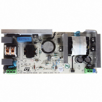
EVL6566A-75WADP STMicroelectronics, EVL6566A-75WADP Datasheet

EVL6566A-75WADP
Specifications of EVL6566A-75WADP
Available stocks
Related parts for EVL6566A-75WADP
EVL6566A-75WADP Summary of contents
Page 1
Constant voltage and constant current control Low consumption Low voltage operation Low external component count Current sink output stage Easy compensation High ac mains voltage rejection 2kV ESD protection (HBM) Voltage Reference: Fixed output voltage reference 1.25V 0.5% and 1% ...
Page 2
TSM1014 1 Pin Descriptions The table below gives the pin descriptions for both SO8 & MiniSO8 packages. Name Pin # Type VRef 1 Analog Output CC- 2 Analog Input CC+ 3 Analog Input CV- 4 Analog Input CVOUT 5 Analog ...
Page 3
Electrical Characteristics 4 Electrical Characteristics Tamb = 25°C and Vcc = +18V (unless otherwise specified) Symbol Parameter Total Current Consumption Total Supply Current, excluding current Icc 1 in Voltage Reference Vz Vcc clamp voltage Operator 1: Op-amp with non-inverting input ...
Page 4
TSM1014 Figure 1: Internal schematic Figure 2: Typical adapter or battery charger application using TSM1014 Vcc 100K 10K Rsense In the application schematic shown in adapter (or battery charger) to provide an ...
Page 5
Principles of Operation and Application Tips 5 Principles of Operation and Application Tips 5.1 Voltage control The voltage loop is controlled via a first trans-conductance operational amplifier, the resistor bridge R1, R2, and the optocoupler which is directly connected to ...
Page 6
TSM1014 Therefore, for most adapter and battery charger applications, a quarter-watt, or half-watt resistor to make the current sensing function is sufficient. The current sinking outputs of the two trans-conductance operational amplifiers are common (to the output of the IC). ...
Page 7
Principles of Operation and Application Tips 5.5 Voltage clamp The following schematic shows how to realize a low-cost power supply for the TSM1014 (with no additional windings).Please pay attention to the fact that in the particular case presented here, this ...
Page 8
TSM1014 6 Package Mechanical Data DIM. MIN. A 1.35 A1 0.10 A2 1.10 B 0.33 C 0.19 D 4. 5.80 h 0.25 L 0.40 k ddd 8/10 SO-8 MECHANICAL DATA mm. TYP MAX. MIN. 1.75 0.053 ...
Page 9
Package Mechanical Data TSM1014 9/10 ...
Page 10
... No license is granted by implication or otherwise under any patent or patent rights of STMicroelectronics. Specifications mentioned in this publication are subject to change without notice. This publication supersedes and replaces all information previously supplied. STMicroelectronics products are not authorized for use as critical components in life support devices or systems without express written approval of STMicroelectronics ...


