EVL6566A-75WES4 STMicroelectronics, EVL6566A-75WES4 Datasheet - Page 11
EVL6566A-75WES4
Manufacturer Part Number
EVL6566A-75WES4
Description
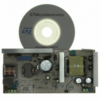
BOARD DEMO FOR L6563/LL6566A
Manufacturer
STMicroelectronics
Type
Power Factor Correctionr
Specifications of EVL6566A-75WES4
Main Purpose
AC/DC, Primary and Secondary Side with PFC
Outputs And Type
1, Isolated
Power - Output
75W
Voltage - Output
19V
Current - Output
4A
Voltage - Input
90 ~ 264VAC
Regulator Topology
Flyback
Board Type
Fully Populated
Utilized Ic / Part
L6563, L6566A, TSM1014
Input Voltage
90 V to 264 V
Output Voltage
19 V
Dimensions
78 mm x 170 mm
Product
Power Management Modules
Lead Free Status / RoHS Status
Lead free / RoHS Compliant
Frequency - Switching
-
Lead Free Status / Rohs Status
Lead free / RoHS Compliant
For Use With/related Products
L6563S, L6566A
Other names
497-8834
Available stocks
Company
Part Number
Manufacturer
Quantity
Price


L6563S
4
Table 4.
Supply voltage
Supply current
Multiplier input
Error amplifier
V
Vcc
Symbol
ΔV
V
INVCLAMP
I
V
Vcc
Vcc
start-up
I
ΔVcs
CLAMP
V
MULT
Hys
I
Vcc
I
I
MULT
K
V
qdis
INV
CC
MULT
I
I
INV
restart
q
q
M
Z
On
Off
Operating range
Turn-on threshold
Turn-off threshold
Vcc for resuming from latch
Hysteresis
Zener voltage
Start-up current
Quiescent current
Operating supply current
Idle state quiescent current
Quiescent current
Input bias current
Linear operation range
Internal clamp level
Output max. slope
Gain
Voltage feedback input threshold
Line regulation
Input bias current
Internal clamp level
Electrical characteristics
T
R
Electrical characteristics
J
FF
= -25 to 125 °C, V
(2)
= 1 MΩ between pin VFF and GND; unless otherwise specified.
Parameter
CC
= 12 V, C
Doc ID 16116 Rev 4
Before turn-on, Vcc = 10 V
After turn-on
(1)
(1)
OVP latched
Icc = 20 mA
After turn-on, V
@ 70 kHz
V
V
V
V
V
V
V
I
V
V
V
T
10.3 V < Vcc < 22.5 V
Vcc = 10.3 V to 22.5 V
TBO open, V
I
MULT
INV
J
O
PFC_OK
INV
PFC_OK
RUN
PFC_OK
COMP
MULT
MULT
COMP
MULT
= 25 °C
= 1 nF between pin GD and GND, C
= 1 mA
< V
< V
= 1 mA
= 0 to 3 V
=0 to 0.4 V, V
= 1 V, V
< 2.3 V
= Upper clamp
PFC_OK –
> V
< V
> V
DIS
Test condition
PFC_OK_S
PFC_OK_D
PFC_OK_S
INV
COMP
MULT
= 0 to 4 V
V
FFD
VFF
= 4 V
= 1 V
(3)
AND
OR
OR
= 0.8 V
Electrical characteristics
0 to 3
0.375 0.45 0.525 1/V
2.455
2.475 2.5 2.525
Min. Typ. Max. Unit
10.3
22.5
8.7
2.3
2.2
11
5
9
8
FF
= 1 µF and
2.34
-0.2
180
-0.2
9.5
1.5
2.2
9.5
12
25
90
6
4
5
9
2
2.545
22.5
10.3
150
280
2.7
6.0
2.2
13
28
-1
-1
7
5
3
5
11/43
V/V
mA
mA
mA
mA
mV
µA
µA
µA
µA
V
V
V
V
V
V
V
V
V
V
Related parts for EVL6566A-75WES4
Image
Part Number
Description
Manufacturer
Datasheet
Request
R

Part Number:
Description:
BOARD EVAL FOR L6566A
Manufacturer:
STMicroelectronics
Datasheet:

Part Number:
Description:
STMicroelectronics [RIPPLE-CARRY BINARY COUNTER/DIVIDERS]
Manufacturer:
STMicroelectronics
Datasheet:
Part Number:
Description:
STMicroelectronics [LIQUID-CRYSTAL DISPLAY DRIVERS]
Manufacturer:
STMicroelectronics
Datasheet:

Part Number:
Description:
BOARD EVAL FOR MEMS SENSORS
Manufacturer:
STMicroelectronics
Datasheet:
Part Number:
Description:
NPN TRANSISTOR POWER MODULE
Manufacturer:
STMicroelectronics
Datasheet:
Part Number:
Description:
TURBOSWITCH ULTRA-FAST HIGH VOLTAGE DIODE
Manufacturer:
STMicroelectronics
Datasheet:
Part Number:
Description:
Manufacturer:
STMicroelectronics
Datasheet:
Part Number:
Description:
DIODE / SCR MODULE
Manufacturer:
STMicroelectronics
Datasheet:
Part Number:
Description:
DIODE / SCR MODULE
Manufacturer:
STMicroelectronics
Datasheet:
Part Number:
Description:
Search -----> STE16N100
Manufacturer:
STMicroelectronics
Datasheet:
Part Number:
Description:
Search ---> STE53NA50
Manufacturer:
STMicroelectronics
Datasheet:
Part Number:
Description:
NPN Transistor Power Module
Manufacturer:
STMicroelectronics
Datasheet: