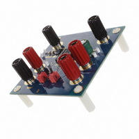
ISL8201MEVAL1Z Intersil, ISL8201MEVAL1Z Datasheet - Page 10

ISL8201MEVAL1Z
Manufacturer Part Number
ISL8201MEVAL1Z
Description
BOARD EVAL STEP-DOWN POL ISL8201
Manufacturer
Intersil
Datasheets
1.ISL8201MIRZ-T.pdf
(16 pages)
2.ISL8201MEVAL1Z.pdf
(9 pages)
3.ISL8201MEVAL1Z.pdf
(16 pages)
Specifications of ISL8201MEVAL1Z
Main Purpose
DC/DC, Step Down
Outputs And Type
1, Non-Isolated
Voltage - Output
1.5V
Current - Output
10A
Voltage - Input
1 ~ 20 V
Regulator Topology
Buck
Frequency - Switching
600kHz
Board Type
Fully Populated
Utilized Ic / Part
ISL8201
Lead Free Status / RoHS Status
Lead free / RoHS Compliant
Power - Output
-
Lead Free Status / Rohs Status
Compliant
If the V
different supply that comes up after P
go through its cycle, but with no output voltage ramp. When
V
zero up to the final expected voltage (at close to 100% duty
cycle, with COMP/EN pin >4V). If V
be excessive inrush current charging the output capacitors
(only the beginning of the ramp, from zero to V
here). If this is not acceptable, then consider changing the
sequencing of the power supplies, sharing the same supply,
or adding sequencing logic to the COMP/EN pin to delay the
soft-start until the V
Considerations” on page 11).
If ISL8201M is disabled after soft-start (by pulling COMP/EN
pin low), and afterwards enabled (by releasing the
COMP/EN pin), then the full initialization (including OCP
sample) will take place. However, there is no new OCP
sampling during overcurrent retries. If the output is shorted
to GND during soft-start, the OCP will handle it, as described
in the next section.
Overcurrent Protection (OCP)
The overcurrent function protects the converter from a
shorted output by using the low side MOSFET
ON-resistance, r
(R
This method enhances the converter's efficiency and
reduces cost by eliminating a current sensing resistor. If
overcurrent is detected, the output immediately shuts off. It
cycles the soft-start function in a hiccup mode (2 dummy
soft-start time-outs, then up to one real one) to provide fault
protection. If the shorted condition is not removed, this cycle
will continue indefinitely.
IN
SET
500mV/ diV
FIGURE 18. PRE-BIASED START-UP - OVERCHARGED
turns on, the output will follow the ramp of the V
) programs the overcurrent trip level.
IN
for the synchronous buck converter is from a
DS(ON)
IN
supply is ready (see “Input Voltage
, to monitor the current. A resistor
VOUT
10
IN
VCC
is too fast, there may
, the soft-start will
OUT
matters
IN
from
ISL8201M
I
R
Following POR (and 6.8ms delay), the ISL8201M initiates
the overcurrent protection sample and hold operation. The
low side gate driver is disabled to allow an internal 21.5µA
current source to develop a voltage across R
ISL8201M samples this voltage (which is referenced to the
PGND pin) at the ISET pin, and holds it in a counter and
DAC combination. This sampled voltage is held internally as
the overcurrent set point, for as long as power is applied, or
until a new sample is taken after coming out of a shut-down.
The actual monitoring of the low side MOSFET
ON-resistance starts 200ns (nominal) after the edge of the
internal PWM logic signal (that creates the rising external
low side gate signal). This is done to allow the gate transition
noise and ringing on the PHASE pin to settle out before
monitoring. The monitoring ends when the internal PWM
edge (and thus low side gate signal) goes low. The OCP can
be detected anywhere within the above window.
If the converter is running at high duty cycles around 75% for
600kHz operation, then the low side gate pulse width may
not be wide enough for the OCP to properly sample the
r
narrow (or not there at all) for 3 consecutive pulses, then the
third pulse will be stretched and/or inserted to the 425ns
minimum width. This allows for OCP monitoring every third
pulse under this condition. This can introduce a small
pulse-width error on the output voltage, which will be
corrected on the next pulse; and the output ripple voltage will
have an unusual 3-clock pattern, which may look like jitter.
The overcurrent function will trip at a peak inductor current
(I
where:
I
R
pins.
r
and 9mΩ @ (V
Note: ISL8201M has integrated 3.57kΩ resistance (R
Therefore, the equivalent resistance of R
expressed in Equation 3:
The scale factor of 2 doubles the trip point of the MOSFET
voltage drop, compared to the setting on the R
The OC trip point varies in a system mainly due to the
MOSFET r
temperature). To avoid overcurrent tripping in the normal
operating load range, find the R
and with Steps 1 to 3:
PEAK
SET
DS(ON)
DS(ON)
PEAK
SET
SET
is the internal I
is equivalent resistance between ISET and PGND
=
) determined by Equation 2:
=
. For those cases, if the low side gate signal is too
is typically 6.1mΩ @ (V
R
------------------------------------------------------ -
R
2
------------------------------------------- -
SET-EX
SET-EX
×
DS(ON)
I
r
SET
DS ON
PVCC
(
×
+
×
variations (i.e. over process, current and
R
R
R
)
SET
SET
SET-IN
SET-IN
= V
current source (21.5µA typical).
GS
= 4.5V, I
PVCC
SET
resistor from Equation 4,
DS
= V
= 30A).
GS
SET
= 10V, I
SET
can be
SET
. The
DS
resistor.
July 16, 2009
SET-IN
= 30A)
FN6657.1
(EQ. 2)
(EQ. 3)
).


