NCP1052GEVB ON Semiconductor, NCP1052GEVB Datasheet - Page 8
NCP1052GEVB
Manufacturer Part Number
NCP1052GEVB
Description
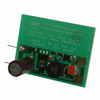
EVAL BOARD FOR NCP1052G
Manufacturer
ON Semiconductor
Specifications of NCP1052GEVB
Design Resources
NCP1052 Eval Board BOM NCP1052GEVB Gerber Files NCP1052 Demo Board Schematic
Main Purpose
AC/DC, Non-Isolated
Outputs And Type
1, Non-Isolated
Power - Output
1.2W
Voltage - Output
120V
Current - Output
100mA
Voltage - Input
85 ~ 265VAC
Regulator Topology
Boost, Buck
Frequency - Switching
136kHz
Board Type
Fully Populated
Utilized Ic / Part
NCP1052
Lead Free Status / RoHS Status
Lead free / RoHS Compliant
For Use With/related Products
NCP1052G
Other names
NCP1052GEVBOS


2. Tested junction temperature range for the NCP105X series:
3. Maximum package power dissipation limits must be observed.
4. Guaranteed by design only.
5. Adjust di/dt to reach I
6. Consult factory for additional options including test and trim for output power accuracy.
ELECTRICAL CHARACTERISTICS
temperature range that applies (Note 2), unless otherwise noted.)
POWER SWITCH CIRCUIT
CURRENT LIMIT AND THERMAL PROTECTION
STARTUP CONTROL
Power Switch Circuit On−State Resistance
NCP1050, NCP1051, NCP1052 (I
NCP1053, NCP1054, NCP1055 (I
Power Switch Circuit & Startup Breakdown Voltage
(I
Power Switch Circuit & Startup Circuit Off−State Leakage Current
(V
(V
Switching Characteristics (R
Current Limit Threshold (T
Conversion Power Deviation (T
Propagation Delay, Current Limit Threshold to Power Switch Circuit Output
Thermal Protection (V
Startup/V
Undervoltage Lockout Threshold Voltage, V
Startup Circuit Output Current (Power Switch Circuit Output = 40 V)
V
V
Minimum Start−up Drain Voltage (I
Output Fault Condition Auto Restart
(V
D(off)
CC
CC
DS
DS
CC
T
T
T
T
Turn−on Time (90% to 10%)
Turn−off Time (10% to 90%)
NCP1050
NCP1051
NCP1052
NCP1053
NCP1054
NCP1055
NCP1050, NCP1051, NCP1052
NCP1053, NCP1054, NCP1055
Shutdown (Junction Temperature Increasing)
Hysteresis (Junction Temperature Decreasing)
Startup Threshold/V
Minimum Operating/V
Hysteresis
T
T
T
T
Average Switching Duty Cycle
Frequency
J
J
J
J
= 0 V
J
J
= V
J
J
= 650 V) T
= 650 V)
T
Capacitor = 10 mF, Power Switch Circuit Output = 40 V)
= −40 to 125°C
= −40 to 125°C
= 25°C
= 125°C
= 25°C
= 125°C
= 25°C
= 25°C
= 100 mA, T
low
CC(on)
CC
= −40°C
Regulation
− 0.2 V
T
J
J
A
= 25°C
= 125°C
= 25°C)
CC
lim
CC
= 8.6 V) (Note 2, 3, 4)
CC
T
in 4.0 msec.
J
Regulation Peak (V
high
= 25°C) (Note 5)
L
Valley Voltage After Turn−On
= 50 W, V
Characteristics
J
= +125°C
= 25°C) (Note 6)
D
D
start
= 50 mA)
= 100 mA)
= 0.5 mA, V
DS
(V
set for I
CC
CC
CC
Decreasing
= 8.0 V, for typical values T
Increasing)
D
CC
= 0.7 I
= V
CC(on)
http://onsemi.com
Iim
)
− 0.2 V)
8
J
= 25°C, for min/max values, T
V
V
Symbol
V
R
V
V
CC(reset)
I
I
start(min)
DS(off)
(BR)DS
2
DS(on)
t
CC(on)
CC(off)
I
D
T
I
f
PLH
V
start
t
t
T
f
lim
OSC
on
off
rst
sd
rst
H
H
Min
700
186
279
372
493
632
140
8.0
7.0
4.0
5.4
4.5
4.6
3.5
93
−
−
−
−
−
−
−
−
−
−
−
−
−
−
−
−
J
is the operating junction
13.4
Typ
100
200
300
400
530
680
135
160
160
8.5
7.5
1.0
4.5
6.3
5.6
6.0
3.5
22
42
10
23
25
15
20
10
75
−
0
−
−
Max
107
214
321
428
567
728
9.0
8.0
5.0
7.2
8.0
6.6
7.0
30
55
15
28
40
80
10
20
−
−
−
−
−
−
−
−
−
−
%A
Unit
mA
mA
mA
°C
Hz
ns
ns
%
W
V
V
V
V
2
Hz
Related parts for NCP1052GEVB
Image
Part Number
Description
Manufacturer
Datasheet
Request
R

Part Number:
Description:
ON Semiconductor [VOLTAGE REGULATOR]
Manufacturer:
ON Semiconductor
Datasheet:
Part Number:
Description:
357-036-542-201 CARDEDGE 36POS DL .156 BLK LOPRO
Manufacturer:
ON Semiconductor
Datasheet:
Part Number:
Description:
357-036-542-201 CARDEDGE 36POS DL .156 BLK LOPRO
Manufacturer:
ON Semiconductor
Datasheet:
Part Number:
Description:
357-036-542-201 CARDEDGE 36POS DL .156 BLK LOPRO
Manufacturer:
ON Semiconductor
Datasheet:
Part Number:
Description:
357-036-542-201 CARDEDGE 36POS DL .156 BLK LOPRO
Manufacturer:
ON Semiconductor
Datasheet:
Part Number:
Description:
357-036-542-201 CARDEDGE 36POS DL .156 BLK LOPRO
Manufacturer:
ON Semiconductor
Datasheet:
Part Number:
Description:
357-036-542-201 CARDEDGE 36POS DL .156 BLK LOPRO
Manufacturer:
ON Semiconductor
Datasheet:
Part Number:
Description:
357-036-542-201 CARDEDGE 36POS DL .156 BLK LOPRO
Manufacturer:
ON Semiconductor
Datasheet:
Part Number:
Description:
357-036-542-201 CARDEDGE 36POS DL .156 BLK LOPRO
Manufacturer:
ON Semiconductor
Datasheet:
Part Number:
Description:
357-036-542-201 CARDEDGE 36POS DL .156 BLK LOPRO
Manufacturer:
ON Semiconductor
Datasheet:
Part Number:
Description:
357-036-542-201 CARDEDGE 36POS DL .156 BLK LOPRO
Manufacturer:
ON Semiconductor
Datasheet:
Part Number:
Description:
Manufacturer:
ON Semiconductor
Datasheet:
Part Number:
Description:
Manufacturer:
ON Semiconductor
Datasheet:
Part Number:
Description:
Manufacturer:
ON Semiconductor
Datasheet: