EVAL-AD5415EBZ Analog Devices Inc, EVAL-AD5415EBZ Datasheet - Page 15
EVAL-AD5415EBZ
Manufacturer Part Number
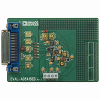
EVAL-AD5415EBZ
Description
BOARD EVALUATION FOR AD5415
Manufacturer
Analog Devices Inc
Specifications of EVAL-AD5415EBZ
Number Of Dac's
2
Number Of Bits
12
Outputs And Type
2, Differential
Sampling Rate (per Second)
2.47M
Data Interface
Serial
Settling Time
120ns
Dac Type
Current
Voltage Supply Source
Single
Operating Temperature
-40°C ~ 125°C
Utilized Ic / Part
AD5415
Lead Free Status / RoHS Status
Lead free / RoHS Compliant


GENERAL DESCRIPTION
DAC SECTION
The AD5415 is a 12-bit, dual-channel, current output DAC
consisting of standard inverting R-2R ladder configuration.
Figure 33 shows a simplified diagram of a single channel of the
AD5415. The feedback resistor R
of R is typically 10 kΩ (with a minimum of 8 kΩ and a
maximum of 12 kΩ). If I
potential, a constant current flows into each ladder leg,
regardless of the digital input code. Therefore, the input
resistance presented at V
Access is provided to the V
the DAC, making the device extremely versatile and allowing it
to be configured in several operating modes, such as unipolar
output, bipolar output, or single-supply mode.
CIRCUIT OPERATION
Unipolar Mode
Using a single op amp, this device can easily be configured to
provide 2-quadrant multiplying operation or a unipolar output
voltage swing, as shown in Figure 34.
V
REF
A
2R
S1
R
DAC DATA LATCHES
AND DRIVERS
2R
Figure 33. Simplified Ladder
S2
R
OUT
REF
2R
S3
REF
1 and I
is always constant.
, R
AGND
NOTES
1. DAC B OMITTED FOR CLARITY.
2. C1 PHASE COMPENSATION (1pF TO 2pF) MAY BE REQUIRED
FB
R
FB
IF A1 IS A HIGH SPEED AMPLIFIER.
, I
OUT
R2_3A
has a value of 2R. The value
OUT
R2A
R3A
2R
2 are kept at the same
S12
1, and I
V
2R
DD
V
REF
R3
2R
R2
2R
OUT
R
R1A
A
2 terminals of
R
I
I
OUT
OUT
SYNC
FB
R1
2R
μCONTROLLER
A
12-BIT DAC A
Figure 34. Unipolar Operation
1A
2A
AD5415
SCLK
Rev. B | Page 15 of 32
R
R
2R
FB
SDIN
AGND
GND
I
I
OUT
OUT
R
When an output amplifier is connected in unipolar mode, the
output voltage is given by
where:
D is the fractional representation, in the range of 0 to 4,095, of
the digital word loaded to the DAC.
n is the number of bits.
Note that the output voltage polarity is opposite the V
polarity for dc reference voltages. This DAC is designed to
operate with either negative or positive reference voltages. The
V
the on and off states of the DAC switches.
This DAC is also designed to accommodate ac reference input
signals in the range of −10 V to +10 V.
With a fixed 10 V reference, the circuit in Figure 34 gives a
unipolar 0 V to −10 V output voltage swing. When V
ac signal, the circuit performs 2-quadrant multiplication.
Table 5 shows the relationship between digital code and
expected output voltage for unipolar operation.
Table 5. Unipolar Code
Digital Input
1111 1111 1111
1000 0000 0000
0000 0000 0001
0000 0000 0000
FB
DD
1A
2A
A
power pin is only used by the internal digital logic to drive
V
AGND
OUT
C1
= − V
A1
REF
V
OUT
× D /2
= 0V TO –V
n
IN
Analog Output (V)
−V
−V
−V
−V
REF
REF
REF
REF
(4,095/4,096)
(2,048/4,096) = −V
(1/4,096)
(0/4,096) = 0
AD5415
IN
REF
is an
REF
/2
Related parts for EVAL-AD5415EBZ
Image
Part Number
Description
Manufacturer
Datasheet
Request
R


Part Number:
Description:
BOARD EVAL FOR SI270X-A
Manufacturer:
Silicon Laboratories Inc
Datasheet:

Part Number:
Description:
BUCK CONV REF DESIGN KIT IP1201
Manufacturer:
International Rectifier
Datasheet:
Part Number:
Description:
BOARD DEMO SYNC DUAL BUCK CNVTER
Manufacturer:
International Rectifier
Datasheet:
Part Number:
Description:
BOARD DEMO SYNC BUCK CONVETER
Manufacturer:
International Rectifier
Datasheet:

Part Number:
Description:
EVALBOARD/EB Omnidirectional microphone - Analog
Manufacturer:
Analog Devices
Datasheet:
Part Number:
Description:
EVALBOARD/EB Omnidirectional microphone - Analog
Manufacturer:
Analog Devices
Datasheet:


Part Number:
Description:
BOARD EVAL LED DRIVER LT3756
Manufacturer:
Linear Technology
Datasheet:

Part Number:
Description:
BOARD EVAL FOR AD7741/7742
Manufacturer:
Analog Devices Inc
Datasheet:

Part Number:
Description:
±1.7g Dual-Axis IMEMS Accelerometer Evaluation Board
Manufacturer:
Analog Devices Inc
Datasheet:

Part Number:
Description:
IC MULTIPLIER ANALOG 8-SOIC T/R
Manufacturer:
Analog Devices Inc
Datasheet:

Part Number:
Description:
IC ANALOG MULTIPLIER 8-DIP
Manufacturer:
Analog Devices Inc
Datasheet:
Part Number:
Description:
IC ANALOG MULTIPLIER 8-SOIC
Manufacturer:
Analog Devices Inc
Datasheet:
Part Number:
Description:
IC ANALOG MULTIPLIER 8-DIP
Manufacturer:
Analog Devices Inc
Datasheet: