LM3423MHBKBSTEV/NOPB National Semiconductor, LM3423MHBKBSTEV/NOPB Datasheet - Page 10
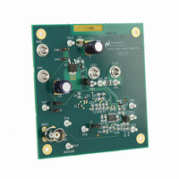
LM3423MHBKBSTEV/NOPB
Manufacturer Part Number
LM3423MHBKBSTEV/NOPB
Description
BOARD EVAL BUCK BOOST LM3423
Manufacturer
National Semiconductor
Series
PowerWise®r
Specifications of LM3423MHBKBSTEV/NOPB
Current - Output / Channel
1A
Outputs And Type
1, Non-Isolated
Voltage - Output
35V
Features
Dimmable
Voltage - Input
4.5 ~ 35V
Utilized Ic / Part
LM3423
Lead Free Status / RoHS Status
Lead free / RoHS Compliant
Other names
LM3423MHBKBSTEV


www.national.com
CURRENT REGULATORS
Current regulators can be designed to accomplish three basic
functions: buck, boost, and buck-boost. All three topologies
in their most basic form contain a main switching MosFET, a
recirculating diode, an inductor and capacitors. The
LM3421/23 is designed to drive a ground referenced NFET
which is perfect for a standard boost regulator. Buck and
buck-boost regulators, on the other hand, usually have a high-
side switch. When driving an LED load, a ground referenced
load is often not necessary, therefore a ground referenced
switch can be used to drive a floating load instead. The
LM3421/23 can then be used to drive all three basic topolo-
gies as shown in the Basic Topology Schematics section.
Other topologies such as the SEPIC and flyback converter
(both derivatives of the buck-boost) can be implemented as
well.
Looking at the buck-boost design, the basic operation of a
current regulator can be analyzed. During the time that the
NFET (Q1) is turned on (t
energy in the inductor (L1) while the output capacitor (C
provides energy to the LED load. When Q1 is turned off
(t
and L1 provides energy to both C
1
operating in CCM.
The average output LED current (I
average inductor current (I
trolled, I
input voltage or output voltage, the ideal duty cycle (D) is var-
ied to regulate I
D is a function of the conversion ratio:
Buck
Boost
Buck-boost
OFF
shows the inductor current (i
), the re-circulating diode (D1) becomes forward biased
LED
will be well regulated. As the system changes
L
and ultimately I
ON
L
), the input voltage source stores
) , therefore if I
L
LED
(t)) waveform for a regulator
O
. For any current regulator,
LED
and the LED load.
FIGURE 1. Ideal CCM Regulator Inductor Current i
) is proportional to the
L
is tightly con-
Figure
O
)
10
PREDICTIVE OFF-TIME (PRO) CONTROL
PRO control is used by the LM3421/23 to control I
combination of average peak current control and a one-shot
off-timer that varies with input voltage. The LM3421/23 uses
peak current control to regulate the average LED current
through an array of HBLEDs. This method of control uses a
series resistor in the LED path to sense LED current and can
use either a series resistor in the MosFET path or the MosFET
R
feed forward. D is indirectly controlled by changes in both
t
Even though the off-time control is quasi-hysteretic, the input
voltage proportionality in the off-timer creates an essentially
constant switching frequency over the entire operating range
for boost and buck-boost topologies. The buck topology can
be designed to give constant ripple over either input voltage
or output voltage, however switching frequency is only con-
stant at a specific operating point .
This type of control minimizes the control loop compensation
necessary in many switching regulators, simplifying the de-
sign process. The averaging mechanism in the peak detec-
tion control loop provides extremely accurate LED current
regulation over the entire operating range.
PRO control was designed to mitigate “current mode
instability” (also called “sub-harmonic oscillation”) found in
standard peak current mode control when operating near or
above 50% duty cycles. When using standard peak current
mode control with a fixed switching frequency, this condition
is present, regardless of the topology. However, using a con-
stant off-time approach, current mode instability cannot oc-
cur, enabling easier design and control.
Predictive off-time advantages:
•
•
The only disadvantage is that synchronization to an external
reference frequency is generally not available.
OFF
DS-ON
There is no current mode instability at any duty cycle.
Higher duty cycles / voltage transformation ratios are
possible, especially in the boost regulator.
and t
for both cycle-by-cycle current limit and input voltage
ON
, which vary depending on the operating point.
L
(t)
30067398
LED
. It is a
Related parts for LM3423MHBKBSTEV/NOPB
Image
Part Number
Description
Manufacturer
Datasheet
Request
R

Part Number:
Description:
National Semiconductor [8-Bit D/A Converter]
Manufacturer:
National Semiconductor
Datasheet:
Part Number:
Description:
National Semiconductor [Media Coprocessor]
Manufacturer:
National Semiconductor
Datasheet:
Part Number:
Description:
Digitally Controlled Tone and Volume Circuit with Stereo Audio Power Amplifier, Microphone Preamp Stage and National 3D Sound
Manufacturer:
National Semiconductor
Datasheet:
Part Number:
Description:
Digitally Controlled Tone and Volume Circuit with Stereo Audio Power Amplifier, Microphone Preamp Stage and National 3D Sound
Manufacturer:
National Semiconductor
Datasheet:
Part Number:
Description:
AC97 Rev 2 Codec with Sample Rate Conversion and National 3D Sound
Manufacturer:
National Semiconductor
Part Number:
Description:
Manufacturer:
National Semiconductor
Datasheet:
Part Number:
Description:
Manufacturer:
National Semiconductor
Datasheet:
Part Number:
Description:
General Purpose, Low Voltage, Low Power, Rail-to-Rail Output Operational Amplifiers
Manufacturer:
National Semiconductor
Datasheet:
Part Number:
Description:
8-bit 20 MSPS flash A/D converter.
Manufacturer:
National Semiconductor
Datasheet:
Part Number:
Description:
Low Noise Quad Operational Amplifier
Manufacturer:
National Semiconductor
Datasheet:
Part Number:
Description:
Quad Differential Line Receivers
Manufacturer:
National Semiconductor
Datasheet:
Part Number:
Description:
Quad High Speed Trapezoidal? Bus Transceiver
Manufacturer:
National Semiconductor
Datasheet:
Part Number:
Description:
Dual Line Receiver
Manufacturer:
National Semiconductor
Datasheet:
Part Number:
Description:
TTL to 10k ECL Level Translator with Latch
Manufacturer:
National Semiconductor
Datasheet: