NCP5006EVB ON Semiconductor, NCP5006EVB Datasheet
NCP5006EVB
Manufacturer Part Number
NCP5006EVB
Description
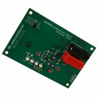
EVAL BOARD FOR NCP5006
Manufacturer
ON Semiconductor
Specifications of NCP5006EVB
Design Resources
NCP5006 Demo Board BOM NCP5006EVB Gerber Files NCP5006 Demo Board Schematic
Current - Output / Channel
15mA
Outputs And Type
1, Non-Isolated
Voltage - Output
22V
Voltage - Input
3.6V
Utilized Ic / Part
NCP5006
Core Chip
NCP5006
Topology
Boost
No. Of Outputs
1
Development Tool Type
Hardware - Eval/Demo Board
Mcu Supported Families
NCP5006
Lead Free Status / RoHS Status
Lead free / RoHS Compliant
Features
-
Lead Free Status / Rohs Status
Lead free / RoHS Compliant
For Use With/related Products
NCP5006
Other names
NCP5006EVBOS


10/19/2004
Test Procedure:
1. Make sure the power supply is OFF.
2. Make sure the power supply is preset to 3.60 V.
3. Make sure the power supply is current limited to 500 mA.
4. Connect the power supply to the banana plugs. Positive supply to Vbat, negative supply to GND.
DC power supply, minimum
3.6 V/500 mA, Preferred
TEKTRONIX PS2520G
Current probe, Preferred
TEKTRONIX TCP202
Test Procedure for the NCP 5006
Table 1: Required Equipment
minimum of two channels, Preferred
Digital voltmeter, Preferred FLUKE
Oscilloscope, 100 MHz bandwidth,
TEKTRONIX TDS784
Analogue probes, 100
MHz bandwidth
minimum, Preferred
TEKTRONIX P6139A
Evaluation Board
One NCP5006
Related parts for NCP5006EVB
Image
Part Number
Description
Manufacturer
Datasheet
Request
R

Part Number:
Description:
Compact Backlight LED Boost Driver
Manufacturer:
ON Semiconductor
Datasheet:
Part Number:
Description:
ON Semiconductor [VOLTAGE REGULATOR]
Manufacturer:
ON Semiconductor
Datasheet:
Part Number:
Description:
357-036-542-201 CARDEDGE 36POS DL .156 BLK LOPRO
Manufacturer:
ON Semiconductor
Datasheet:
Part Number:
Description:
357-036-542-201 CARDEDGE 36POS DL .156 BLK LOPRO
Manufacturer:
ON Semiconductor
Datasheet:
Part Number:
Description:
357-036-542-201 CARDEDGE 36POS DL .156 BLK LOPRO
Manufacturer:
ON Semiconductor
Datasheet:
Part Number:
Description:
357-036-542-201 CARDEDGE 36POS DL .156 BLK LOPRO
Manufacturer:
ON Semiconductor
Datasheet:
Part Number:
Description:
357-036-542-201 CARDEDGE 36POS DL .156 BLK LOPRO
Manufacturer:
ON Semiconductor
Datasheet:
Part Number:
Description:
357-036-542-201 CARDEDGE 36POS DL .156 BLK LOPRO
Manufacturer:
ON Semiconductor
Datasheet:
Part Number:
Description:
357-036-542-201 CARDEDGE 36POS DL .156 BLK LOPRO
Manufacturer:
ON Semiconductor
Datasheet:
Part Number:
Description:
357-036-542-201 CARDEDGE 36POS DL .156 BLK LOPRO
Manufacturer:
ON Semiconductor
Datasheet:
Part Number:
Description:
357-036-542-201 CARDEDGE 36POS DL .156 BLK LOPRO
Manufacturer:
ON Semiconductor
Datasheet:
Part Number:
Description:
357-036-542-201 CARDEDGE 36POS DL .156 BLK LOPRO
Manufacturer:
ON Semiconductor
Datasheet:
Part Number:
Description:
Manufacturer:
ON Semiconductor
Datasheet:
Part Number:
Description:
Manufacturer:
ON Semiconductor
Datasheet:
NCP5006EVB Summary of contents
Page 1
DC power supply, minimum 3.6 V/500 mA, Preferred TEKTRONIX PS2520G Current probe, Preferred TEKTRONIX TCP202 Test Procedure: 1. Make sure the power supply is OFF. 2. Make sure the power supply is preset to 3. Make sure ...
Page 2
If current monitor is necessary, connect a short jumper (5 cm) across JP1 to read current and connect the current sensor. 6. Connect one analogue probe to pin Vout to read the output voltage. 7. Connect a short DVM ...
Page 3
Typical Operating Waveforms ...
Page 4
...
Page 5
...