NCP1351LEDGEVB ON Semiconductor, NCP1351LEDGEVB Datasheet - Page 4
NCP1351LEDGEVB
Manufacturer Part Number
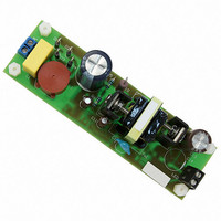
NCP1351LEDGEVB
Description
EVAL BOARD FOR NCP1351LEDG
Manufacturer
ON Semiconductor
Datasheets
1.NCP1351APG.pdf
(27 pages)
2.NCP1351LEDGEVB.pdf
(11 pages)
3.NCP1351LEDGEVB.pdf
(3 pages)
Specifications of NCP1351LEDGEVB
Design Resources
NCP1351 EVB BOM NCP1351LEDGEVB Gerber Files NCP1351LED EVB Schematic
Current - Output / Channel
700mA
Outputs And Type
1, Isolated
Voltage - Output
33V
Features
Short-Circuit Protection
Voltage - Input
85 ~ 265 V
Utilized Ic / Part
NCP1351
Core Chip
NCP1351
Topology
Flyback
No. Of Outputs
1
Output Current
700mA
Output Voltage
33V
Development Tool Type
Hardware - Eval/Demo Board
Leaded Process Compatible
Yes
Rohs Compliant
Yes
Lead Free Status / RoHS Status
Lead free / RoHS Compliant
For Use With/related Products
NCP1351LEDG
Other names
NCP1351LEDGEVBOS


primary of the inductor (above) if we define a term k equal
to;
assuming operation in boundary conduction mode:
I
VALLEY
September 2008, Rev. 2
I
I
Looking at the waveform of the current flowing in the
And use the equation:
Then we can determine the inductance we require.
If k = 2 then we are in boundary conduction mode as
the ripple current equals twice the average pulse
current, so setting k to 2:
Thus we can now find the primary ripple current
The average input current, I
AVE
I
k
Δ
PK
L
L
1
I
=
I
=
=
L
Δ
100
(
=
=
V
I
I
1
IN
V
283
L
f
(
(min)
×
IN
δT
80
SW
...........................................................(Eq.8)
10
(min)
SW
×
kP
L
δ
×
10
3
80
MAX
T
. 0
IN
×
ON
−
47
×
2
6
)
0 .
×
. 0
2
=
)
100
2
47
×
V
.........................................(Eq.9)
T
25
IN
SW
×
Lf
(min)
10
=
SW
AVE
283
δ
3
max
, is:
=
. 1
μ
32
H
A
............(Eq.10)
........(Eq.11)
∆I
L
t
DN06040/D
www.onsemi.com
peak primary current is 1.32 A.
sense resistor for dissipation purposes. For a stepped-
sawtooth waveform of this type the equation is:
allowing for a drop across the resistor of 0.8 V:
resistors typically cost more.
offset resistor; this has a bias current of 270 µA in it so we
can determine the resistor value:
The average pulse current, I
Demonstrating that ∆I
We can calculate the RMS current in the MOSFET and
Thus:
We can also determine the current sense resistor,
The total power dissipation is:
Two 1.2 Ω resistors in parallel will be used as sub 1 Ω
The threshold voltage for the current sense is set by an
I
I
I
I
......................................................................... (Eq.15)
R
P
R
1
RMS
RMS
AVE
D
OFFSET
SENSE
(
=
sense
δ
I
=
=
=
=
AVE
max
)
V
=
. 0
526
I
=
=
≅
1
IN
P
V
665
170
V
I
=
IN
I
(min)
DROP
δ
I
RMS
SENSE
mA
PK
BIAS
. 0
. 0
×
1
mW
313
2
=
47
R
+
=
. 0
=
SENSE
25
80
1
3
. 1
47
0
=
270
⎛ Δ
⎜ ⎜
⎝
32
8 .
L
=
662
2
×
does equal twice I
=
0
313
I
I
×
=
1
L
8 .
. 0
10
1
. 0
⎞
⎟ ⎟
⎠
mA
1
+
526
2
, is:
mA
61
−
6
1
3
........................ (Eq.14)
≅
...................... (Eq.13)
⎛
⎜
⎝
Ω
2
2
×
................... (Eq.12)
3
×
................. (Eq.16)
0 .
. 0
. 1
. 0
61
32
k
665
Ω
........ (Eq.17)
1
...... (Eq.18)
and that the
⎞
⎟
⎠
2
4
Related parts for NCP1351LEDGEVB
Image
Part Number
Description
Manufacturer
Datasheet
Request
R

Part Number:
Description:
ON Semiconductor [VOLTAGE REGULATOR]
Manufacturer:
ON Semiconductor
Datasheet:
Part Number:
Description:
357-036-542-201 CARDEDGE 36POS DL .156 BLK LOPRO
Manufacturer:
ON Semiconductor
Datasheet:
Part Number:
Description:
357-036-542-201 CARDEDGE 36POS DL .156 BLK LOPRO
Manufacturer:
ON Semiconductor
Datasheet:
Part Number:
Description:
357-036-542-201 CARDEDGE 36POS DL .156 BLK LOPRO
Manufacturer:
ON Semiconductor
Datasheet:
Part Number:
Description:
357-036-542-201 CARDEDGE 36POS DL .156 BLK LOPRO
Manufacturer:
ON Semiconductor
Datasheet:
Part Number:
Description:
357-036-542-201 CARDEDGE 36POS DL .156 BLK LOPRO
Manufacturer:
ON Semiconductor
Datasheet:
Part Number:
Description:
357-036-542-201 CARDEDGE 36POS DL .156 BLK LOPRO
Manufacturer:
ON Semiconductor
Datasheet:
Part Number:
Description:
357-036-542-201 CARDEDGE 36POS DL .156 BLK LOPRO
Manufacturer:
ON Semiconductor
Datasheet:
Part Number:
Description:
357-036-542-201 CARDEDGE 36POS DL .156 BLK LOPRO
Manufacturer:
ON Semiconductor
Datasheet:
Part Number:
Description:
357-036-542-201 CARDEDGE 36POS DL .156 BLK LOPRO
Manufacturer:
ON Semiconductor
Datasheet:
Part Number:
Description:
357-036-542-201 CARDEDGE 36POS DL .156 BLK LOPRO
Manufacturer:
ON Semiconductor
Datasheet:
Part Number:
Description:
Manufacturer:
ON Semiconductor
Datasheet:
Part Number:
Description:
Manufacturer:
ON Semiconductor
Datasheet:
Part Number:
Description:
Manufacturer:
ON Semiconductor
Datasheet: