STEVAL-ILL027V1 STMicroelectronics, STEVAL-ILL027V1 Datasheet - Page 16
STEVAL-ILL027V1
Manufacturer Part Number
STEVAL-ILL027V1
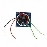
Description
BOARD EVAL LED DRIVER FOR L6562A
Manufacturer
STMicroelectronics
Datasheets
1.L6562ADTR.pdf
(26 pages)
2.STEVAL-ILL027V1.pdf
(4 pages)
3.STEVAL-ILL027V1.pdf
(23 pages)
Specifications of STEVAL-ILL027V1
Design Resources
STEVAL-ILL027V1 Schematics STEVAL-ILL027V1 BOM STEVAL-ILL027V1 Gerber Files
Current - Output / Channel
260mA
Outputs And Type
1, Non-Isolated
Voltage - Output
70V
Features
Short-Circuit Protection
Voltage - Input
120VAC
Utilized Ic / Part
L6562A
Product
Display Modules
Lead Free Status / RoHS Status
Lead free by exemption / RoHS compliant by exemption
Other names
497-10170


STEVAL-ILL027V2 demonstration board
16/23
capacitor package on the original design. The capacitors C8 and C10 470 nF / 305 V were
selected, because, thanks to this value, EMI behavior is fulfilled as demonstrated in
Figure 16
Maximum input voltage can be up to 362 V (265 V x √ 2) and therefore at least two SMD
resistors must be used for sensing the input voltage. An additional resistor, R16 = 100 k Ω,
is connected in series with R12 and the additional resistor, R15 = 510 k Ω, is connected in
series with R9.
Also the voltage divider used for the MULT pin is recalculated in order to have the correct
voltage on the MULT pin. The highest voltage on the MULT pin is presented for maximum
input voltage 265 V AC. In this case the voltage on the MULT pin is done by the following
equation:
Equation 14
Absolute maximum rating for the MULT pin is 8 V, which means that such a margin is high
enough to correctly operate even with maximum input voltage 265 V AC.
The next modification is to change the sense resistors R6 and R11, because these resistors
are used to set the level of constant LED current. The resistors R6 and R11 were replaced
by resistor 2R7.
Regarding the power MOSFET capability, it is possible to calculate its maximum drain
source voltage. Assume that maximum output LED voltage is approximately 72 V (18 LEDs
with maximum forward voltage 4 V) and then maximum drain source voltage is:
Equation 15
For this kind of topology the switching losses are higher for higher input voltage and
therefore the power MOSFET with better current capability is selected for the input voltage
230 V AC. The STD11NM50N power MOSFET is used for the STEVAL-ILL027V2
demonstration board.
Maximum reverse voltage on diode D7 is also 445 V, when the power MOSFET is ON.
Ultrafast diode D7 STTH3R06A with maximum repetitive reverse voltage 600 V was
selected for this application.
Electrolytic capacitor C5 = 10 µF / 35 V is replaced by the small SMD ceramic capacitor
2.2 µF / 50 V as there is a size limitation on the board.
The transformer's number of turns can be used exactly the same as on the original design,
because the output LED voltage is transformed to the auxiliary winding when the MOSFET
is OFF in the same ratio as on the original design. For the output LED power 18 W and
constant LED current 350 mA, the LED voltage is 51.4 V. This voltage is reflected to the
auxiliary winding. The transformer isolation is 500 V DC and so the transformer can be used
in this application for EU input voltage range. The others components are without any
change.
and
17
V ds
. The capacitor C9 was replaced by the capacitor 150 nF / 305 V AC.
Vmult
=
=
Vin max
Vin max
--------------------------------------- -
R3
+
Doc ID 16815 Rev 2
R9
×
+
×
R15
R3
2
+
V
=
led max
-------------------------------------------------------------------- -
12000
362
+
510000
=
×
265
12000
×
+
510000
2
+
72
=
=
445V
4.2V
AN3111
Related parts for STEVAL-ILL027V1
Image
Part Number
Description
Manufacturer
Datasheet
Request
R

Part Number:
Description:
BOARD EVAL FOR MEMS SENSORS
Manufacturer:
STMicroelectronics
Datasheet:

Part Number:
Description:
KIT DEV STARTER ST10F276Z5
Manufacturer:
STMicroelectronics
Datasheet:

Part Number:
Description:
BOARD EVAL HDMI $ VIDEO SWITCH
Manufacturer:
STMicroelectronics
Datasheet:

Part Number:
Description:
BOARD DEMO ACCELEROMETER DIL24
Manufacturer:
STMicroelectronics
Datasheet:

Part Number:
Description:
BOARD STLM75/STDS75/ST72F651
Manufacturer:
STMicroelectronics
Datasheet:

Part Number:
Description:
EVAL BOARD 3AXIS MEMS ACCELLRMTR
Manufacturer:
STMicroelectronics
Datasheet:

Part Number:
Description:
BOARD EVAL 8BIT MICRO + TDE1708
Manufacturer:
STMicroelectronics
Datasheet:

Part Number:
Description:
EVAL BOARD A/D TS4657
Manufacturer:
STMicroelectronics
Datasheet:

Part Number:
Description:
BOARD ADAPTER 20DIP LIS3LV02DL
Manufacturer:
STMicroelectronics
Datasheet:

Part Number:
Description:
BOARD DEMO STM8S207R6/LIS331DLH
Manufacturer:
STMicroelectronics
Datasheet:

Part Number:
Description:
STMicroelectronics [RIPPLE-CARRY BINARY COUNTER/DIVIDERS]
Manufacturer:
STMicroelectronics
Datasheet:
Part Number:
Description:
STMicroelectronics [LIQUID-CRYSTAL DISPLAY DRIVERS]
Manufacturer:
STMicroelectronics
Datasheet:
Part Number:
Description:
BOARD EVAL FOR MEMS SENSORS
Manufacturer:
STMicroelectronics
Datasheet: