MCP6V01DM-VOS Microchip Technology, MCP6V01DM-VOS Datasheet - Page 18
MCP6V01DM-VOS
Manufacturer Part Number
MCP6V01DM-VOS
Description
DEMO BOARD FOR MCP6V01
Manufacturer
Microchip Technology
Specifications of MCP6V01DM-VOS
Channels Per Ic
1 - Single
Amplifier Type
Chopper (Zero-Drift)
Output Type
Rail-to-Rail
Slew Rate
0.5 V/µs
Current - Output / Channel
22mA
Operating Temperature
-40°C ~ 125°C
Voltage - Supply, Single/dual (±)
1.8 V ~ 5.5 V
Board Type
Fully Populated
Utilized Ic / Part
MCP6V01
Silicon Manufacturer
Microchip
Application Sub Type
Operational Amplifier
Kit Application Type
Amplifier
Silicon Core Number
MCP6V01, MCP6V03, MCP6V06, MCP6V08
Kit Contents
Board
Lead Free Status / RoHS Status
Lead free / RoHS Compliant
-3db Bandwidth
-
Current - Supply (main Ic)
-
Lead Free Status / Rohs Status
Lead free / RoHS Compliant


MCP6V01 Input Offset Demo Board User’s Guide
3.3
DS51801A-page 14
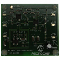
CONNECTING A CHIP SELECT PIN TO GROUND
The DUT can be changed to the MCP6V03 or MCP6V08 op amps with chip select. If
desired, their Chip Select pin (pin 8) can be forced to ground. This is done as follows
(see Figure 3-2):
1. Solder one end of a wire to the DUT’s pin 8. Pin 8 is next to the U1 reference
2. Solder the other end of the wire the closest ground via on the PCB. The striped
FIGURE 3-2:
designator on the PCB (not next to the DUT label)
green arrow to the right in the figure shows the location. The solid green curve
represents the wire.
DUT’s Pin 8
Location and Orientation of DUT.
Draft
Ground Via
© 2009 Microchip Technology Inc.
Related parts for MCP6V01DM-VOS
Image
Part Number
Description
Manufacturer
Datasheet
Request
R

Part Number:
Description:
IC OPAMP AUTO-ZERO SNGL 8SOIC
Manufacturer:
Microchip Technology
Datasheet:

Part Number:
Description:
300 ?A, Auto-Zeroed Op Amps
Manufacturer:
MICROCHIP [Microchip Technology]
Datasheet:
Part Number:
Description:
Op Amps Sngl Auto-Zero Op Amp E temp
Manufacturer:
Microchip Technology

Part Number:
Description:
300 ?a, Auto-zeroed Op Amps
Manufacturer:
Microchip Technology Inc.
Datasheet:
Part Number:
Description:
Manufacturer:
Microchip Technology Inc.
Datasheet:
Part Number:
Description:
Manufacturer:
Microchip Technology Inc.
Datasheet:
Part Number:
Description:
Manufacturer:
Microchip Technology Inc.
Datasheet:
Part Number:
Description:
Manufacturer:
Microchip Technology Inc.
Datasheet:
Part Number:
Description:
Manufacturer:
Microchip Technology Inc.
Datasheet:
Part Number:
Description:
Manufacturer:
Microchip Technology Inc.
Datasheet:
Part Number:
Description:
Manufacturer:
Microchip Technology Inc.
Datasheet: