AS5140 AB austriamicrosystems, AS5140 AB Datasheet - Page 15
AS5140 AB
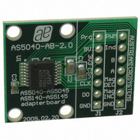
Manufacturer Part Number
AS5140 AB
Description
BOARD ADAPTER AS5140
Manufacturer
austriamicrosystems
Specifications of AS5140 AB
Sensor Type
Magnetic, Rotary Position
Sensing Range
360°
Interface
Serial
Voltage - Supply
5V
Embedded
No
Utilized Ic / Part
AS5140
Lead Free Status / RoHS Status
Lead free by exemption / RoHS compliant by exemption
Sensitivity
-
Other names
AS5140H AB
AS5140H AB
AS5140H AB


AS5140H
Data Sheet - D e t a i l e d D e s c r i p t i o n
Programming Daisy Chained Devices.
the chain
pin Prog. This voltage level exceeds the limits for pin DO, so one of the following precautions must be made during programming:
Due to the parallel connection of CLK and CSn, all connected devices may be programmed simultaneously.
7.2 Incremental Outputs
Three different incremental output modes are possible with quadrature A/B being the default mode.
as well as the step / direction incremental signal (LSB) and the direction bit in clockwise (CW) and counter-clockwise (CCW) direction.
7.2.1 Quadrature A/B Output (Quad A/B Mode)
The phase shift between channel A and B indicates the direction of the magnet movement. Channel A leads channel B at a clockwise rotation of
the magnet (top view) by 90 electrical degrees. Channel B leads channel A at a counter-clockwise rotation.
Figure 8. Incremental Output Modes
7.2.2 LSB Output (Step/Direction Mode)
Output LSB reflects the LSB (least significant bit) of the programmed incremental resolution (OTP Register Bit Div0, Div1). Output Dir provides
information about the rotational direction of the magnet, which may be placed above or below the device (1=clockwise; 0=counter clockwise; top
view). Dir is updated with every LSB change. In both modes (quad A/B, step/direction), the resolution and the index output are user
programmable. The index pulse indicates the zero position and is by default one angular step (1LSB) wide. However, it can be set to three LSBs
by programming the Index-bit of the OTP register accordingly
www.austriamicrosystems.com/AS5140H
Open the connection
Add a Schottky diode between DO and Prog (Anode = DO, Cathode = Prog)
(see Figure
Quad A/B-Mode
Step / Dir-Mode
6). During programming
LSB
Index
Dir
CSn
A
B
DO
t
Incremental outputs valid
→
Prog
during programming, (or)
In Daisy Chain mode, the Prog pin is connected directly to the DO pin of the subsequent device in
(see Programming the AS5140H on page
Clockwise cw
(see Table
Zero Position
Revision 1.4
Mechanical
Index=1
Index=0
3 LSB
1 LSB
20).
Rotation Direction
19), a programming voltage of 7.5V must be applied to
Change
t
Dir valid
Hyst=
2LSB
Figure 8
Zero Position
Mechanical
Counterclockwise ccw
shows the two-channel quadrature
15 - 37
Related parts for AS5140 AB
Image
Part Number
Description
Manufacturer
Datasheet
Request
R

Part Number:
Description:
BOARD DEMO AS5140
Manufacturer:
austriamicrosystems
Datasheet:

Part Number:
Description:
10-bit 360? Programmable Magnetic Rotary Encoder For High Ambient Temperatures Up To 150?c
Manufacturer:
austriamicrosystems
Datasheet:
Part Number:
Description:
IC SWITCH QUAD SPST 14-TSSOP
Manufacturer:
austriamicrosystems
Datasheet:
Part Number:
Description:
IC SWITCH QUAD SPST 14-TSSOP
Manufacturer:
austriamicrosystems
Datasheet:
Part Number:
Description:
IC AMP AUDIO MONO 1.8W 10-MSOP
Manufacturer:
austriamicrosystems
Datasheet:
Part Number:
Description:
IC AMP AUDIO MONO 1.8W 10-MSOP
Manufacturer:
austriamicrosystems
Datasheet:
Part Number:
Description:
IC AMP AUDIO MONO 1.8W 10-MSOP
Manufacturer:
austriamicrosystems
Datasheet:
Part Number:
Description:
IC AMP AUD 1.8W 3DB GAIN 10-MSOP
Manufacturer:
austriamicrosystems
Datasheet:
Part Number:
Description:
IC DRIVER LED 8-DIGIT 24-SOIC
Manufacturer:
austriamicrosystems
Datasheet:
Part Number:
Description:
IC DRIVER LED 8-DIGIT 24-SOIC
Manufacturer:
austriamicrosystems
Datasheet:
Part Number:
Description:
IC, LINE/SPEAKER PHONE CIRCUIT, SOIC-28
Manufacturer:
austriamicrosystems
Datasheet:
Part Number:
Description:
IC MULTI-STANDARD CMOS TELEPHONE SOIC-28
Manufacturer:
austriamicrosystems
Datasheet:
Part Number:
Description:
IC MULTI-STANDARD CMOS TELEPHONE SOIC-28
Manufacturer:
austriamicrosystems
Datasheet:
Part Number:
Description:
IC MULTI-STANDARD CMOS TELEPHONE SOIC-28
Manufacturer:
austriamicrosystems
Datasheet:
Part Number:
Description:
CABGA 64 (7x7)
Manufacturer:
austriamicrosystems
Datasheet: