AS5140 AB austriamicrosystems, AS5140 AB Datasheet - Page 19
AS5140 AB
Manufacturer Part Number
AS5140 AB
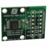
Description
BOARD ADAPTER AS5140
Manufacturer
austriamicrosystems
Specifications of AS5140 AB
Sensor Type
Magnetic, Rotary Position
Sensing Range
360°
Interface
Serial
Voltage - Supply
5V
Embedded
No
Utilized Ic / Part
AS5140
Lead Free Status / RoHS Status
Lead free by exemption / RoHS compliant by exemption
Sensitivity
-
Other names
AS5140H AB
AS5140H AB
AS5140H AB


AS5140H
Data Sheet - D e t a i l e d D e s c r i p t i o n
7.6 Programming the AS5140H
Note: A detailed description of the austriamicrosystems low voltage polyfuse OTP programming method is given in Application Note AN514X-
After power-on, programming the AS5140H is enabled with the rising edge of CSn with Prog = high and CLK = low. The AS5140H programming
is a one-time-programming (OTP) method, based on polysilicon fuses. The advantage of this method is that a programming voltage of only 3.3V
is required for programming. The OTP consists of 52 bits, of which 21 bits are available for user programming. The remaining 31 bits contain
factory settings and a unique chip identifier (Chip-ID).
A single OTP cell can be programmed only once. Per default, the cell is “0”; a programmed cell will contain a “1”. While it is not possible to reset
a programmed bit from “1” to “0”, multiple OTP writes are possible, as long as only unprogrammed “0”-bits are programmed to “1”. Independent
of the OTP programming, it is possible to overwrite the OTP register temporarily with an OTP write command at any time. This setting will be
cleared and overwritten with the hard programmed OTP settings at each power-up sequence or by a LOAD operation.
The OTP memory can be accessed in several ways:
7.6.1 OTP Memory Assignment
Table 19. OTP Bit Assignment
www.austriamicrosystems.com/AS5140H
Load Operation: The Load operation reads the OTP fuses and loads the contents into the OTP register. Note that the Load operation is
automatically executed after each power-on-reset.
Write Operation: The Write operation allows a temporary modification of the OTP register. It does not program the OTP. This operation can
be invoked multiple times, and will remain set while the chip is supplied with power and while the OTP register is not modified with another
Write or Load operation.
Read Operation: The Read operation reads the contents of the OTP register, for example to verify a Write command or to read the OTP
memory after a Load command.
Program Operation: The Program operation writes the contents of the OTP register permanently into the OTP ROM.
Analog Readback Operation: The Analog Readback operation allows a quantifiable verification of the programming. For each pro-
grammed or unprogrammed bit, there is a representative analog value (in essence, a resistor value) that is read to verify whether a bit has
been successfully programmed or not.
10, which can be downloaded from the austriamicrosystems website. The OTP programming description in this datasheet is for general
information only.
Bit
51
50
49
48
47
46
37
36
35
31
30
18
:
:
:
Symbol
FS 12
mbit1
Index
CCW
FS 0
FS 1
Md0
Md1
Div0
Div1
RA0
RA4
Z0
Z9
:
:
Revision 1.4
Incremental Output Mode Selection
Redundancy Address
10 bit Zero Position
Factory Bit
Factory Bit
Factory Bit
Factory Bit
Function
Direction
19 - 37
Related parts for AS5140 AB
Image
Part Number
Description
Manufacturer
Datasheet
Request
R

Part Number:
Description:
BOARD DEMO AS5140
Manufacturer:
austriamicrosystems
Datasheet:

Part Number:
Description:
10-bit 360? Programmable Magnetic Rotary Encoder For High Ambient Temperatures Up To 150?c
Manufacturer:
austriamicrosystems
Datasheet:
Part Number:
Description:
IC SWITCH QUAD SPST 14-TSSOP
Manufacturer:
austriamicrosystems
Datasheet:
Part Number:
Description:
IC SWITCH QUAD SPST 14-TSSOP
Manufacturer:
austriamicrosystems
Datasheet:
Part Number:
Description:
IC AMP AUDIO MONO 1.8W 10-MSOP
Manufacturer:
austriamicrosystems
Datasheet:
Part Number:
Description:
IC AMP AUDIO MONO 1.8W 10-MSOP
Manufacturer:
austriamicrosystems
Datasheet:
Part Number:
Description:
IC AMP AUDIO MONO 1.8W 10-MSOP
Manufacturer:
austriamicrosystems
Datasheet:
Part Number:
Description:
IC AMP AUD 1.8W 3DB GAIN 10-MSOP
Manufacturer:
austriamicrosystems
Datasheet:
Part Number:
Description:
IC DRIVER LED 8-DIGIT 24-SOIC
Manufacturer:
austriamicrosystems
Datasheet:
Part Number:
Description:
IC DRIVER LED 8-DIGIT 24-SOIC
Manufacturer:
austriamicrosystems
Datasheet:
Part Number:
Description:
IC, LINE/SPEAKER PHONE CIRCUIT, SOIC-28
Manufacturer:
austriamicrosystems
Datasheet:
Part Number:
Description:
IC MULTI-STANDARD CMOS TELEPHONE SOIC-28
Manufacturer:
austriamicrosystems
Datasheet:
Part Number:
Description:
IC MULTI-STANDARD CMOS TELEPHONE SOIC-28
Manufacturer:
austriamicrosystems
Datasheet:
Part Number:
Description:
IC MULTI-STANDARD CMOS TELEPHONE SOIC-28
Manufacturer:
austriamicrosystems
Datasheet:
Part Number:
Description:
CABGA 64 (7x7)
Manufacturer:
austriamicrosystems
Datasheet: