AS5140 AB austriamicrosystems, AS5140 AB Datasheet - Page 23
AS5140 AB
Manufacturer Part Number
AS5140 AB
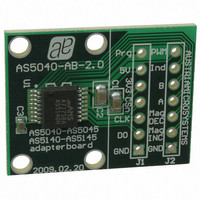
Description
BOARD ADAPTER AS5140
Manufacturer
austriamicrosystems
Specifications of AS5140 AB
Sensor Type
Magnetic, Rotary Position
Sensing Range
360°
Interface
Serial
Voltage - Supply
5V
Embedded
No
Utilized Ic / Part
AS5140
Lead Free Status / RoHS Status
Lead free by exemption / RoHS compliant by exemption
Sensitivity
-
Other names
AS5140H AB
AS5140H AB
AS5140H AB


AS5140H
Data Sheet - D e t a i l e d D e s c r i p t i o n
Figure 15. Enabling the Alignment Mode
Figure 16. Exiting Alignment Mode
7.8 3.3V / 5V Operation
The AS5140H operates either at 3.3V ±10% or at 5V ±10%. This is made possible by an internal 3.3V Low-Dropout (LDO) voltage regulator. The
internal supply voltage is always taken from the output of the LDO, meaning that the internal blocks are always operating at 3.3V. For 3.3V
operation, the LDO must be bypassed by connecting VDD3V3 with VDD5V
For 5V operation, the 5V supply is connected to pin VDD5V, while VDD3V3 (LDO output) must be buffered by a 2.2...10µF capacitor, which is
supposed to be placed close to the supply pin
external load.
The output voltage of the digital interface I/O’s corresponds to the voltage at pin VDD5V, as the I/O buffers are supplied from this pin
17). A buffer capacitor of 100nF is recommended in both cases close to pin VDD5V.
Note that pin VDD3V3 must always be buffered by a capacitor. It must not be left floating, as this may cause an instable internal 3.3V supply
voltage, which may lead to larger than normal jitter of the measured angle.
www.austriamicrosystems.com/AS5140H
CSn
Prog
CSn
Prog
(see Figure
2µs
min.
17). The VDD3V3 output is intended for internal use only. It must not be loaded with an
min.
2µs
AlignMode enable
exit AlignMode
Revision 1.4
(see Figure
17).
Read-out
Read-out
via SSI
via SSI
(see Figure
23 - 37
Related parts for AS5140 AB
Image
Part Number
Description
Manufacturer
Datasheet
Request
R

Part Number:
Description:
BOARD DEMO AS5140
Manufacturer:
austriamicrosystems
Datasheet:

Part Number:
Description:
10-bit 360? Programmable Magnetic Rotary Encoder For High Ambient Temperatures Up To 150?c
Manufacturer:
austriamicrosystems
Datasheet:
Part Number:
Description:
IC SWITCH QUAD SPST 14-TSSOP
Manufacturer:
austriamicrosystems
Datasheet:
Part Number:
Description:
IC SWITCH QUAD SPST 14-TSSOP
Manufacturer:
austriamicrosystems
Datasheet:
Part Number:
Description:
IC AMP AUDIO MONO 1.8W 10-MSOP
Manufacturer:
austriamicrosystems
Datasheet:
Part Number:
Description:
IC AMP AUDIO MONO 1.8W 10-MSOP
Manufacturer:
austriamicrosystems
Datasheet:
Part Number:
Description:
IC AMP AUDIO MONO 1.8W 10-MSOP
Manufacturer:
austriamicrosystems
Datasheet:
Part Number:
Description:
IC AMP AUD 1.8W 3DB GAIN 10-MSOP
Manufacturer:
austriamicrosystems
Datasheet:
Part Number:
Description:
IC DRIVER LED 8-DIGIT 24-SOIC
Manufacturer:
austriamicrosystems
Datasheet:
Part Number:
Description:
IC DRIVER LED 8-DIGIT 24-SOIC
Manufacturer:
austriamicrosystems
Datasheet:
Part Number:
Description:
IC, LINE/SPEAKER PHONE CIRCUIT, SOIC-28
Manufacturer:
austriamicrosystems
Datasheet:
Part Number:
Description:
IC MULTI-STANDARD CMOS TELEPHONE SOIC-28
Manufacturer:
austriamicrosystems
Datasheet:
Part Number:
Description:
IC MULTI-STANDARD CMOS TELEPHONE SOIC-28
Manufacturer:
austriamicrosystems
Datasheet:
Part Number:
Description:
IC MULTI-STANDARD CMOS TELEPHONE SOIC-28
Manufacturer:
austriamicrosystems
Datasheet:
Part Number:
Description:
CABGA 64 (7x7)
Manufacturer:
austriamicrosystems
Datasheet: