DV164122 Microchip Technology, DV164122 Datasheet - Page 36
DV164122
Manufacturer Part Number
DV164122
Description
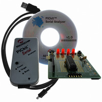
ANALYZER SRL PICKIT W/DEMO BOARD
Manufacturer
Microchip Technology
Series
PICkit™r
Type
MCUr
Specifications of DV164122
Contents
PICkit™ Serial Analyzer, 28-pin Demo Board, USB Cable, and Software with Documentation CD
Processor To Be Evaluated
PIC16F886
Interface Type
USB
Silicon Manufacturer
Microchip
Kit Application Type
Interface
Application Sub Type
USB
Silicon Family Name
PIC16F
Kit Contents
PICkit Serial Analyzer, Demo Board, USB Cable, Software
Rohs Compliant
Yes
Lead Free Status / RoHS Status
Not applicable / Not applicable
For Use With/related Products
PIC16F886
For Use With
PKSERIAL-SPI1 - BOARD DEMO PICKIT SERIAL SPIPKSERIAL-I2C1 - BOARD DEMO PICKIT SERIAL I2C
Lead Free Status / Rohs Status
Lead free / RoHS Compliant
Other names
Q3260228
Available stocks
Company
Part Number
Manufacturer
Quantity
Price
Company:

Part Number:
DV164122
Manufacturer:
Microchip Technology
Quantity:
135
Company:
Part Number:
DV164122
Manufacturer:
MICROCHIP
Quantity:
12 000


4.6
DS51647B-page 30
COMMUNICATIONS: BASIC OPERATIONS
• AUX1 Default State – AUX1 communication line – default state (0 | 1)
• AUX2 Default State – AUX2 communication line – default state (0 | 1)
• AUX1 Direction – AUX1 communication line – direction: 1: input, 0: output
• AUX2 Direction – AUX2 communication line – direction: 1: input, 0: output
The I
• Communications: Basic Operations from the tool bar, or
• Communications > Basic Operations from the menu bar
The I
communications commands, Read and Write and Receive.
Read performs a combination Write then Read commands to the target device (refer to
the I
structure of the command is:
• Start bit (S_)
• Slave Address[W] – Enter the slave address of the device to communicate with.
• Word Address – Enter the word address
• Restart (RS),
• Slave Address[R] – The slave address with the write bit set will be automatically
• Byte Count – Enter the number of bytes to be read
• Stop bit (P_)
Write performs a write operation to the target device (refer to The I
reference in Section 4.1 “Introduction” above). The basic structure of the command
is:
• Start bit (S_)
• Slave Address[W] – Enter the slave address of the device to communicate with.
• Word Address – Enter the word address
• Data – Enter up to eight bytes of data
• Stop bit (P_)
The command will be logged in the Transactions window. A listing of the command
abbreviations is given in Table 4-2.
Receive issues a simple read command to the target device (refer to The I2C Specifi-
cation reference in Section 4.1 “Introduction” above). The basic structure of the com-
mand is:
• Start bit (S_)
• Slave Address[W] – Enter the slave address of the device to communicate with.
The write bit should be set to indicate a read operation.
• Byte Count – Enter the number of bytes to receive
• Stop bit (P_)
- Switch Off (not depressed) – blink LED1, LED2 off
- Switch ON (depressed) – blink LED2, LED1 off
The write bit should be cleared to indicate a write operation
entered when the Slave Address[W] has been entered
The write bit should be cleared to indicate a write operation.
Note:
2
2
2
C Specification reference in Section 4.1 “Introduction” above). The basic
C Basic Operations window can be opened by selecting:
C Basic Operations window is shown in Figures 4-3. There are three basic
The “x” indicates the value is a hexadecimal number. Clicking on “x” will
toggle it to a “d” indicating that the value is a decimal number.
© 2007 Microchip Technology Inc.
2
C Specification
Related parts for DV164122
Image
Part Number
Description
Manufacturer
Datasheet
Request
R

Part Number:
Description:
Manufacturer:
Microchip Technology Inc.
Datasheet:
Part Number:
Description:
Manufacturer:
Microchip Technology Inc.
Datasheet:
Part Number:
Description:
Manufacturer:
Microchip Technology Inc.
Datasheet:
Part Number:
Description:
Manufacturer:
Microchip Technology Inc.
Datasheet:
Part Number:
Description:
Manufacturer:
Microchip Technology Inc.
Datasheet:
Part Number:
Description:
Manufacturer:
Microchip Technology Inc.
Datasheet:
Part Number:
Description:
Manufacturer:
Microchip Technology Inc.
Datasheet:
Part Number:
Description:
Manufacturer:
Microchip Technology Inc.
Datasheet: