ATSAM3U-EK Atmel, ATSAM3U-EK Datasheet - Page 25
ATSAM3U-EK
Manufacturer Part Number
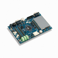
ATSAM3U-EK
Description
KIT EVAL FOR AT91SAM3U CORTEX
Manufacturer
Atmel
Type
MCUr
Datasheets
1.ATSAM3U-EK.pdf
(2 pages)
2.ATSAM3U-EK.pdf
(61 pages)
3.ATSAM3U-EK.pdf
(1171 pages)
4.ATSAM3U-EK.pdf
(53 pages)
Specifications of ATSAM3U-EK
Contents
Board
Processor To Be Evaluated
SAM3U
Data Bus Width
32 bit
Interface Type
RS-232, USB
Operating Supply Voltage
3 V
Silicon Manufacturer
Atmel
Core Architecture
ARM
Core Sub-architecture
Cortex - M3
Silicon Core Number
SAM3U4E
Silicon Family Name
SAM3U
Kit Contents
Board CD Docs
Rohs Compliant
Yes
For Use With/related Products
AT91SAM3U
Lead Free Status / RoHS Status
Lead free / RoHS Compliant
Available stocks
Company
Part Number
Manufacturer
Quantity
Price
Company:

Part Number:
ATSAM3U-EK
Manufacturer:
Atmel
Quantity:
10


6.4
6.5
6.6
6.7
6430DS–ATARM–28-Mar-11
Test Pin
NRST Pin
NRSTB Pin
ERASE Pin
The JTAGSEL pin is used to select the JTAG boundary scan when asserted at a high level. It
integrates a permanent pull-down resistor of about 15 kΩ to GNDBU, so that it can be left uncon-
nected for normal operations.
By default, the JTAG Debug Port is active. If the debugger host wants to switch to the Serial
Wire Debug Port, it must provide a dedicated JTAG sequence on TMS/SWDIO and
TCK/SWCLK which disables the JTAG-DP and enables the SW-DP. When the Serial Wire
Debug Port is active, TDO/TRACESWO can be used for trace.
The asynchronous TRACE output (TRACESWO) is multiplexed with TDO. So the asynchronous
trace can only be used with SW-DP, not JTAG-DP.
All the JTAG signals are supplied with VDDIO except JTAGSEL, supplied by VDDBU.
The TST pin is used for JTAG Boundary Scan Manufacturing Test or fast flash programming
mode of the SAM3U series. The TST pin integrates a permanent pull-down resistor of about 15
kΩ to GND, so that it can be left unconnected for normal operations. To enter fast programming
mode, see the “Fast Flash Programming Interface” section of the product datasheet. For more
on the manufacturing and test mode, refer to the “Debug and Test” section of the product
datasheet.
The NRST pin is bidirectional. It is handled by the on-chip reset controller and can be driven low
to provide a reset signal to the external components or asserted low externally to reset the
microcontroller. It will reset the Core and the peripherals, except the Backup region (RTC, RTT
and Supply Controller). There is no constraint on the length of the reset pulse and the reset con-
troller can guarantee a minimum pulse length.
The NRST pin integrates a permanent pull-up resistor to VDDIO of about 100 kΩ.
The NRSTB pin is input only and enables asynchronous reset of the SAM3U when asserted low.
The NRSTB pin integrates a permanent pull-up resistor of about 15 kΩ. This allows connection
of a simple push button on the NRSTB pin as a system-user reset. In all modes, this pin will
reset the chip including the Backup region (RTC, RTT and Supply Controller). It reacts as the
Power-on reset. It can be used as an external system reset source. In harsh environments, it is
recommended to add an external capacitor (10 nF) between NRSTB and VDDBU. (For filtering
values refer to “I/O Characteristics” in the “Electrical Characteristics” section of the product
datasheet.)
It embeds an anti-glitch filter.
The ERASE pin is used to reinitialize the Flash content and some of its NVM bits. It integrates a
permanent pull-down resistor of about 15 kΩ to GND, so that it can be left unconnected for nor-
mal operations.
This pin is debounced by SCLK to improve the glitch tolerance. When the ERASE pin is tied high
during less than 100 ms, it is not taken into account. The pin must be tied high during more than
220 ms to perform the reinitialization of the Flash.
SAM3U Series
25
Related parts for ATSAM3U-EK
Image
Part Number
Description
Manufacturer
Datasheet
Request
R

Part Number:
Description:
AT91 ARM Thumb-based Microcontrollers
Manufacturer:
ATMEL [ATMEL Corporation]
Datasheet:

Part Number:
Description:
DEV KIT FOR AVR/AVR32
Manufacturer:
Atmel
Datasheet:

Part Number:
Description:
INTERVAL AND WIPE/WASH WIPER CONTROL IC WITH DELAY
Manufacturer:
ATMEL Corporation
Datasheet:
Part Number:
Description:
Low-Voltage Voice-Switched IC for Hands-Free Operation
Manufacturer:
ATMEL Corporation
Datasheet:
Part Number:
Description:
MONOLITHIC INTEGRATED FEATUREPHONE CIRCUIT
Manufacturer:
ATMEL Corporation
Datasheet:
Part Number:
Description:
AM-FM Receiver IC U4255BM-M
Manufacturer:
ATMEL Corporation
Datasheet:
Part Number:
Description:
Monolithic Integrated Feature Phone Circuit
Manufacturer:
ATMEL Corporation
Datasheet:
Part Number:
Description:
Multistandard Video-IF and Quasi Parallel Sound Processing
Manufacturer:
ATMEL Corporation
Datasheet:
Part Number:
Description:
High-performance EE PLD
Manufacturer:
ATMEL Corporation
Datasheet:
Part Number:
Description:
8-bit Flash Microcontroller
Manufacturer:
ATMEL Corporation
Datasheet:
Part Number:
Description:
2-Wire Serial EEPROM
Manufacturer:
ATMEL Corporation
Datasheet: