ATSAM3U-EK Atmel, ATSAM3U-EK Datasheet - Page 58
ATSAM3U-EK
Manufacturer Part Number
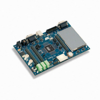
ATSAM3U-EK
Description
KIT EVAL FOR AT91SAM3U CORTEX
Manufacturer
Atmel
Type
MCUr
Datasheets
1.ATSAM3U-EK.pdf
(2 pages)
2.ATSAM3U-EK.pdf
(61 pages)
3.ATSAM3U-EK.pdf
(1171 pages)
4.ATSAM3U-EK.pdf
(53 pages)
Specifications of ATSAM3U-EK
Contents
Board
Processor To Be Evaluated
SAM3U
Data Bus Width
32 bit
Interface Type
RS-232, USB
Operating Supply Voltage
3 V
Silicon Manufacturer
Atmel
Core Architecture
ARM
Core Sub-architecture
Cortex - M3
Silicon Core Number
SAM3U4E
Silicon Family Name
SAM3U
Kit Contents
Board CD Docs
Rohs Compliant
Yes
For Use With/related Products
AT91SAM3U
Lead Free Status / RoHS Status
Lead free / RoHS Compliant
Available stocks
Company
Part Number
Manufacturer
Quantity
Price
Company:

Part Number:
ATSAM3U-EK
Manufacturer:
Atmel
Quantity:
10


58
Doc Rev
6430BS
SAM3U Series
Comments
Introduction:
Section 1. ”SAM3U
2x TWIs (SAM3U1C/2C/4C have 1), up to 5x SPIs SAM3U1C/2C/4C have 4),
Table 1-1, “Configuration
SAM3U4/3/2C rows FWUP replaces NO in FWUP,SHDN pins column
updated, SM cell removed; UART moved to peripheral area, added Flash Unique block, removed 12B from
ADC block, added SysTick counter and Fmax 96 MHz to M3 block. FWUP replaces WKUP in fig 2-1, FWUP
added to fig 2-2
Figure 2-2 ”100-pin SAM3U4/2/1C Block
Table 3-1, “Signal Description
details given in footnote.
VDDIN, VDDOUT added to table.
”Serial Wire/JTAG Debug Port (SWJ-DP)”
status of pulldowns and pullups specified.
Section 4. ”Package and
Section 4.1 ”SAM3U4/2/1E Package and Pinout”
pinouts finalized in datasheet.
Section 5.5.1 ”Backup
Figure 5-4 ”Wake-up
Table 5-1, “Low Power Mode Configuration
“Previous state saved.
Section 6.6 ”NRSTB
Section 6. ”Input/Output
Section 6.1 ”General Purpose I/O Lines (GPIO)”
Line Considerations”.
Figure 6-1 ”On-Die Termination
Section 6.8 “PIO Controllers”, removed.
Section 8. ”Product
Section 9.
Memories”.
Section 9.1.3.5 ”Security Bit
Table 7-3, “SAM3U Master to Slave
Section 7.2 ”APB/AHB
Table 11-3, “Multiplexing on PIO Controller B
Section 12.10.1 ”12-bit High Speed
“Quadrature Decoder Logic” on page
Section 12.10.1 ”12-bit High Speed
Section 12.10.2 ”10-bit Low Power
Figure 2-1 ”144-pin SAM3U4/2/1E Block Diagram”
”Memories”, now comprises
Description”, Updated: 52 Kbytes of SRAM. 4x USARTs (SAM3U1C/2C/4C have 3), up to
Mapping”, title changed from “Memories”.
Pin”, VDDIO changed to VDDBU
Source”, BODEN replaced by SMEN.
Mode”, BOD replaced by Supply Monitor/SM. FWUP → Falling Edge Detector.
Bridges”, reference to ADC updated “10-bit ADC, 12-bit ADC (ADC12B)”.
Lines”, replaces Section 5.8 “Programmable I/O Lines”.
Pinout”, reorganized according to product.
Summary”,EBI column updated, 8 bits for SAM3U1C/2C/4C
Feature”, updated
List”, Schmitt Trigger added
schematic”, added.
ADC”, Ksample values updated on 2nd item of list.
ADC”,
ADC”, 2nd item on list updated.
Access”, Slave 9, High Speed Peripheral Bridge line added.
49, properly stated in list of TC functions.
Section 9.1 ”Embedded Memories”
Diagram”, NWR1/NBS1, NXRP0, A0 removed from block diagram.
replaced ICE and JTAG. This section of the table updated
Section 12.10.2 ”10-bit Low Power
Summary”, PIO state in Low Power Modes, backup mode is;
(PIOB)”, ADC12B2, ADC12B3 properly listed.
and
and
and
Section 6.2 ”System I/O
Section 4.2 ”SAM3U4/2/1C Package and
Figure 2-2 ”100-pin SAM3U4/2/1C Block Diagram”
”PIO Controller - PIOA - PIOB -
and
Lines”, replace Section 6. “I/O
ADC”, titles changed.
Section 9.2 ”External
PIOC”. exception
Pinout”,
6430DS–ATARM–28-Mar-11
Change
Request
Ref.
6400
6642
6482/6642
rfo
6480
rfo
6471/rfo
6607
rfo
6645
6646
6481/rfo
6663
6397
rfo
Related parts for ATSAM3U-EK
Image
Part Number
Description
Manufacturer
Datasheet
Request
R

Part Number:
Description:
AT91 ARM Thumb-based Microcontrollers
Manufacturer:
ATMEL [ATMEL Corporation]
Datasheet:

Part Number:
Description:
DEV KIT FOR AVR/AVR32
Manufacturer:
Atmel
Datasheet:

Part Number:
Description:
INTERVAL AND WIPE/WASH WIPER CONTROL IC WITH DELAY
Manufacturer:
ATMEL Corporation
Datasheet:
Part Number:
Description:
Low-Voltage Voice-Switched IC for Hands-Free Operation
Manufacturer:
ATMEL Corporation
Datasheet:
Part Number:
Description:
MONOLITHIC INTEGRATED FEATUREPHONE CIRCUIT
Manufacturer:
ATMEL Corporation
Datasheet:
Part Number:
Description:
AM-FM Receiver IC U4255BM-M
Manufacturer:
ATMEL Corporation
Datasheet:
Part Number:
Description:
Monolithic Integrated Feature Phone Circuit
Manufacturer:
ATMEL Corporation
Datasheet:
Part Number:
Description:
Multistandard Video-IF and Quasi Parallel Sound Processing
Manufacturer:
ATMEL Corporation
Datasheet:
Part Number:
Description:
High-performance EE PLD
Manufacturer:
ATMEL Corporation
Datasheet:
Part Number:
Description:
8-bit Flash Microcontroller
Manufacturer:
ATMEL Corporation
Datasheet:
Part Number:
Description:
2-Wire Serial EEPROM
Manufacturer:
ATMEL Corporation
Datasheet: