DK-MAXII-1270N Altera, DK-MAXII-1270N Datasheet - Page 34
DK-MAXII-1270N
Manufacturer Part Number
DK-MAXII-1270N
Description
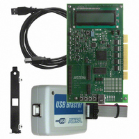
KIT DEV MAXII W/EPM 1270N
Manufacturer
Altera
Series
MAX® IIr
Type
CPLDr
Specifications of DK-MAXII-1270N
Contents
Dev Board, Quartus®II Web Edition, Nios®II Web Edition, Cables, Accessories, Reference Designs and Demos
Silicon Manufacturer
Altera
Core Architecture
CPLD
Core Sub-architecture
MAX
Silicon Core Number
EPM
Silicon Family Name
MAX II
Rohs Compliant
Yes
For Use With/related Products
MAX®II CPLDs
Lead Free Status / RoHS Status
Lead free / RoHS Compliant
Other names
544-2380
Available stocks
Company
Part Number
Manufacturer
Quantity
Price


Reference Designs
2–26
MAX II Development Kit Getting Started User Guide
f
For a detailed explanation of the controller functionality, see White Paper:
MAX II Development Board LCD Controller.
1
Reset Functionality
At any point during game play, pressing the Reset button (S5) will cycle
the board power, stop the game, and reload the design’s programming
file (.pof) into the SRAM (volatile) portion of the MAX II device via the
Configuration Flash Memory. After the file has been reloaded, all
registers are restored to their default value and the design returns to its
initial introduction display.
Reference Design 3: PCI Reference Design
The PCI Reference Design provides an example of how users can
interface the MAX II development board to a PC via the PCI expansion
slots. The design uses Altera’s PCI T32 MegaCore function to interface to
the PCI Bus of any standard PC. All design files are provided in the
<root>/HW/Examples/ReferenceDesigns/PCI_Reference
Design/QuartusProject/DesignFiles directory.
w
Using the Reference Design
1.
2.
Program the MAX II device with the PCI_RefDesign.pof file. (Refer
to
how to load POF files into the MAX II device.)
Register the drivers:
a.
b.
“Programming the MAX II Device” on page 2–4
Development Kit Version 1.1.0
The Slot Game Reference Design has added an extra bit to the
bus input of the LCD controller. It is used to vary the speed of
transactions to the LCD display. For more information on this bit
and its functionality, refer to the lcd_controller.v file in the Slot
Game Reference Design Quartus II Project.
The MAX II PCI demo shows a simple example of how to
generate interrupts. When a user presses one of the switches, an
interrupt is generated. In a PCI system, the interrupts are shared
between many devices. Special care is required that the user
does not press a switch unless the MAX II PCI application is
active.
Open a command prompt (DOS window).
CD to the <root>/Examples/HW/ReferenceDesigns/
PCI_ReferenceDesign/Win2k_XP_Drivers directory.
Altera Corporation
for details on
July 2005
Related parts for DK-MAXII-1270N
Image
Part Number
Description
Manufacturer
Datasheet
Request
R

Part Number:
Description:
KIT DEV MAX V 5M570Z
Manufacturer:
Altera
Datasheet:

Part Number:
Description:
CYCLONE II STARTER KIT EP2C20N
Manufacturer:
Altera
Datasheet:


Part Number:
Description:
CPLD, EP610 Family, ECMOS Process, 300 Gates, 16 Macro Cells, 16 Reg., 16 User I/Os, 5V Supply, 35 Speed Grade, 24DIP
Manufacturer:
Altera Corporation
Datasheet:
Part Number:
Description:
CPLD, EP610 Family, ECMOS Process, 300 Gates, 16 Macro Cells, 16 Reg., 16 User I/Os, 5V Supply, 15 Speed Grade, 24DIP
Manufacturer:
Altera Corporation
Datasheet:
Part Number:
Description:
Manufacturer:
Altera Corporation
Datasheet:
Part Number:
Description:
CPLD, EP610 Family, ECMOS Process, 300 Gates, 16 Macro Cells, 16 Reg., 16 User I/Os, 5V Supply, 30 Speed Grade, 24DIP
Manufacturer:
Altera Corporation
Datasheet:
Part Number:
Description:
High-performance, low-power erasable programmable logic devices with 8 macrocells, 10ns
Manufacturer:
Altera Corporation
Datasheet:
Part Number:
Description:
High-performance, low-power erasable programmable logic devices with 8 macrocells, 7ns
Manufacturer:
Altera Corporation
Datasheet:
Part Number:
Description:
Classic EPLD
Manufacturer:
Altera Corporation
Datasheet:
Part Number:
Description:
High-performance, low-power erasable programmable logic devices with 8 macrocells, 10ns
Manufacturer:
Altera Corporation
Datasheet:
Part Number:
Description:
Manufacturer:
Altera Corporation
Datasheet:
Part Number:
Description:
Manufacturer:
Altera Corporation
Datasheet:
Part Number:
Description:
Manufacturer:
Altera Corporation
Datasheet: