DM240011 Microchip Technology, DM240011 Datasheet - Page 31
DM240011
Manufacturer Part Number
DM240011
Description
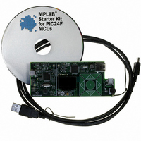
KIT STARTER MPLAB FOR PIC24F MCU
Manufacturer
Microchip Technology
Series
MPLAB®r
Type
MCUr
Datasheet
1.DM240011.pdf
(42 pages)
Specifications of DM240011
Contents
Board, Cable, CD
Processor To Be Evaluated
PIC24F
Data Bus Width
16 bit
Interface Type
USB
Silicon Manufacturer
Microchip
Core Architecture
PIC
Core Sub-architecture
PIC24
Silicon Core Number
PIC24F
Silicon Family Name
PIC24FJxxGBxxx
Kit Contents
Board Cables CD Docs
Lead Free Status / RoHS Status
Lead free / RoHS Compliant
For Use With/related Products
PIC24F
Lead Free Status / Rohs Status
Lead free / RoHS Compliant
Available stocks
Company
Part Number
Manufacturer
Quantity
Price
Company:

Part Number:
DM240011
Manufacturer:
Microchip Technology
Quantity:
135
Company:
Part Number:
DM240011
Manufacturer:
MICROCHIP
Quantity:
12 000


5.1
FIGURE 5-1:
© 2008 Microchip Technology Inc.
APPLICATION FUNCTIONAL OVERVIEW
To Debugger Side
(PIC18F67J50)
Potentiometer
This chapter provides a functional overview of the MPLAB Starter Kit for PIC24F, and
identifies the major hardware components. Topics covered include:
• Application Functional Overview
• Programmer/Debugger Functional Overview
• Board Components
Figure 5-1 illustrates the main functions of the starter kit:
APPLICATION SIDE BLOCK DIAGRAM
The application side of the starter kit is centered on the PIC24F256GB106
microcontroller, which requires very little additional hardware to perform its tasks. All
application code is stored in the device’s Flash program memory. In addition to the
application core, the preloaded demo uses substantial parts of the Microchip USB
Stack Library, the Microchip Memory Disk Drive File System and the Microchip
Graphics Library to function.
The application accepts user inputs from the capacitive touch pad (S1) and the
potentiometer (R44). The microcontroller uses one of its A/D converter channels to
sample and convert the potentiometer’s value to a digital value for the Data Graphing
and Data Capture demos. Five additional A/D channels are used to monitor the
individual touch pads of S1. The values from these channels are analyzed with the
CTMU to determine when a touch-and-release event occurs on any of the pads. The
application firmware determines which action to take based on the application’s current
context.
Keypads
Touch
32 kHz
Crystal
ICSP™
Chapter 5. Hardware
PGC/EMUC
PGD/EMUD
MCLR
AN0
AN8:AN12
SOSCI:SOSCO
PIC24FJ256GB106
MPLAB STARTER KIT FOR PIC24F
PMD7:PMD0
RG6/RG7
RG8/RG9
RF4/RF5
PMCS1
PMWR
PMRD
PMA0
D+/D-
A Receptacle
USB mini-B
Receptacle
Tri-Color
USER’S GUIDE
Display
OLED
LED
USB
DS51725A-page 27
Related parts for DM240011
Image
Part Number
Description
Manufacturer
Datasheet
Request
R

Part Number:
Description:
Manufacturer:
Microchip Technology Inc.
Datasheet:
Part Number:
Description:
Manufacturer:
Microchip Technology Inc.
Datasheet:
Part Number:
Description:
Manufacturer:
Microchip Technology Inc.
Datasheet:
Part Number:
Description:
Manufacturer:
Microchip Technology Inc.
Datasheet:
Part Number:
Description:
Manufacturer:
Microchip Technology Inc.
Datasheet:
Part Number:
Description:
Manufacturer:
Microchip Technology Inc.
Datasheet:
Part Number:
Description:
Manufacturer:
Microchip Technology Inc.
Datasheet:
Part Number:
Description:
Manufacturer:
Microchip Technology Inc.
Datasheet: