DM240011 Microchip Technology, DM240011 Datasheet - Page 32
DM240011
Manufacturer Part Number
DM240011
Description
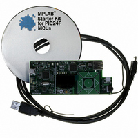
KIT STARTER MPLAB FOR PIC24F MCU
Manufacturer
Microchip Technology
Series
MPLAB®r
Type
MCUr
Datasheet
1.DM240011.pdf
(42 pages)
Specifications of DM240011
Contents
Board, Cable, CD
Processor To Be Evaluated
PIC24F
Data Bus Width
16 bit
Interface Type
USB
Silicon Manufacturer
Microchip
Core Architecture
PIC
Core Sub-architecture
PIC24
Silicon Core Number
PIC24F
Silicon Family Name
PIC24FJxxGBxxx
Kit Contents
Board Cables CD Docs
Lead Free Status / RoHS Status
Lead free / RoHS Compliant
For Use With/related Products
PIC24F
Lead Free Status / Rohs Status
Lead free / RoHS Compliant
Available stocks
Company
Part Number
Manufacturer
Quantity
Price
Company:

Part Number:
DM240011
Manufacturer:
Microchip Technology
Quantity:
135
Company:
Part Number:
DM240011
Manufacturer:
MICROCHIP
Quantity:
12 000


MPLAB Starter Kit for PIC24F User’s Guide
5.2
FIGURE 5-2:
DS51725A-page 28
From Host PC
PROGRAMMER/DEBUGGER FUNCTIONAL OVERVIEW
The microcontroller directly drives the OLED display (LED1) and the tri-color LED (D6,
D10 or D11, depending on the board’s manufacturing option). The microcontroller uses
the Parallel Master Port to drive the OLED through the PMD7:PMD0 data lines, while
PMA0, PMCS2, PMRD and PMWR serve as control signals. A DC boost circuit
comprised of power MOSFET Q4, along with D5 and L3, provides the operating voltage
for the OLED.
The individual channels of the tri-color LED are driven directly by three of the
microcontroller’s PWM modules, assigned to outputs on pins RF4/RF5, RG6/RG7 and
RG8/RG9. Two output pins are used for each PWM to ensure sufficient drive strength
for each LED component.
The microcontroller uses an on-chip USB On-The-Go (OTG) engine and transceiver to
communicate with USB A and mini-B receptacles on the application side. While both
receptacles are populated, only the A receptacle is used in this version of the demo
application. The mini-B receptacle is available for users who may wish to design a
peripheral application.
Figure 5-2 illustrates the debugging/programming operation of the starter kit.
STARTER KIT PROGRAMMER/DEBUGGER BLOCK DIAGRAM
In its default configuration, the Starter Kit functions as a USB bus-powered device.
Power is provided via the USB cable; the nominal 5 volt unregulated supply is regulated
by a Microchip MC1727 3.3 volt low-dropout (LDO) linear regulator. Proper main
system power is indicated by the green LED (D2).
The debugging and programming side of the Starter Kit is controlled by a PIC18F67J50
microcontroller running at 48 MHz. The PIC18F67J50’s built-in USB engine provides
the communications interface between the Starter Kit and the host PC. The
microcontroller manages debugging or programming of the target PIC24FJ256GB106
by controlling the target’s MCLR, PGC1/EMUC1, and PGD1/EMUD1 signals. Target
power is switched on and off via a low V
as a high-side switch. Target clocking is also provided by the PIC18F67J50.
A Microchip 25LC010A serial EEPROM is used to store the starter kit’s serial number
and debug control information.
V
DD
USB mini-B
3.3V LDO
Regulator
to Starter Kit
Jack
V
BUS
USB Data
Power
LED
Debug
Serial EEPROM
LED
PIC18F67J50
25LC010A
CE
12 MHz
Crystal
saturation PNP transistor (Q1) configured
SPI
ICSP™
© 2008 Microchip Technology Inc.
To Application Side
(PIC24FJ256GB106)
Related parts for DM240011
Image
Part Number
Description
Manufacturer
Datasheet
Request
R

Part Number:
Description:
Manufacturer:
Microchip Technology Inc.
Datasheet:
Part Number:
Description:
Manufacturer:
Microchip Technology Inc.
Datasheet:
Part Number:
Description:
Manufacturer:
Microchip Technology Inc.
Datasheet:
Part Number:
Description:
Manufacturer:
Microchip Technology Inc.
Datasheet:
Part Number:
Description:
Manufacturer:
Microchip Technology Inc.
Datasheet:
Part Number:
Description:
Manufacturer:
Microchip Technology Inc.
Datasheet:
Part Number:
Description:
Manufacturer:
Microchip Technology Inc.
Datasheet:
Part Number:
Description:
Manufacturer:
Microchip Technology Inc.
Datasheet: