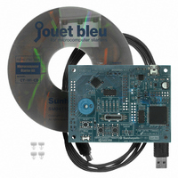
CT-161-CD Fujitsu Semiconductor America Inc, CT-161-CD Datasheet - Page 70

CT-161-CD
Manufacturer Part Number
CT-161-CD
Description
KIT 16LX FOR MB90F387
Manufacturer
Fujitsu Semiconductor America Inc
Series
F²MC-16LXr
Type
MCUr
Specifications of CT-161-CD
Contents
Board, Cable, CD
For Use With/related Products
MB90F387S
Lead Free Status / RoHS Status
Lead free / RoHS Compliant
Other names
865-1103
Available stocks
Company
Part Number
Manufacturer
Quantity
Price
Company:
Part Number:
CT-161-CD
Manufacturer:
Fujitsu Semiconductor America
Quantity:
135
5.2
(corresponding to the telephone call or visitor in the real world) when the event occurs. This
mechanism is the interrupt. A program can be efficient when it uses interrupts. The sample
program described in Chapter 3 uses a procedure for checking the on/off state of the switches
cyclically. However, an interrupt is used in the program, the microcomputer can be notified
of a switch on/off operation by the interrupt when the operation occurs. Therefore, the
processing to cyclically check the on/off state of the switches can be eliminated, and the
efficiency of the program can be increased thereby. This chapter explains how to detect
switch operation by using an interrupt and how to create the program for the operation.
As described in Chapter 3, the board of the Starter Kit has two switches that are connected to
pins P25 and P27 of the microcomputer. Pins P25 and P27 connecting the switches were
used as input ports in the program example described in Chapter 3. These pins can be used
also as external interrupt input pins (INT5 and INT7). The following describes how to detect
switch operation (pressing of a switch) by using an external interrupt input.
Figure 5.2 shows an outline of SW1 connection circuit on the board of the Starter Kit. SW1
is connected to pin INT5 of the microcomputer as shown in Figure 5.2. While SW1 is
released (in the off state), the voltage at pin INT5 of the microcomputer is Vcc (5 V), and the
signal input to pin INT7 is at the high level. When SW1 is pressed (in the on state), the
voltage at pin INT5 becomes the GND level, and the signal input to pin IN5 changes from the
high level to the low level. When SW1 is released subsequently, the signal input to pin INT5
changes from the low level to the high level. When the external interrupt function of pin
INT5 of the microcomputer is used, an interrupt can be generated when the pin status is
changed. In short, this mechanism enables the microcomputer to be informed of switch
operation by the interrupt. SW2 can be handled in a similar way to handle SW1. Because
SW2 is connected to pin INT7 of the microcomputer, an external interrupt is generated at pin
INT7 when SW2 is operated.
How to detect a switch operation by interrupts
Figure 5.2 Connection of SW1 to microcomputer pin (conceptual diagram)
Microcompute
ENIR
ELVR
EIRR
r
-
64
-
Pin INT5
(pin P25)
GND
Vcc
Starter Kit board
SW1
© Fujitsu


