CT-161-CD Fujitsu Semiconductor America Inc, CT-161-CD Datasheet - Page 71
CT-161-CD
Manufacturer Part Number
CT-161-CD
Description
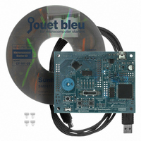
KIT 16LX FOR MB90F387
Manufacturer
Fujitsu Semiconductor America Inc
Series
F²MC-16LXr
Type
MCUr
Specifications of CT-161-CD
Contents
Board, Cable, CD
For Use With/related Products
MB90F387S
Lead Free Status / RoHS Status
Lead free / RoHS Compliant
Other names
865-1103
Available stocks
Company
Part Number
Manufacturer
Quantity
Price
Company:

Part Number:
CT-161-CD
Manufacturer:
Fujitsu Semiconductor America
Quantity:
135


© Fujitsu
5.3
Explained next is the procedure for using pin INT5 as an external interrupt pin. To use pin
INT5 for the input of external interrupt, you should set the I-O direction of the pin to input by
using the port 2 register "DDR2." Handling of DDR2 was described in Chapter 3. Write '0'
to the bit 5 of DDR2. You should also set necessary values in external interrupt registers
"EIRR," "ENIR," and "ELVR" for using pin INT5 as the external interrupt input pin. EIRR
is an 8-bit register that indicates external interrupt factors. ENIR is an 8-bit register that
enables and disables external interrupts.
conditions for external interrupt detection.
Assume the processing to detect the SW1 operation from the off state to the on state by using
an interrupt. When SW1 is pressed, the signal input to pin INT5 changes from the high level
to the low level (as described before). When values are set in external interrupt registers in
steps (1) to (4) below, the external interrupt function enables the microcomputer to detect the
change (falling edge) of the signal input to pin INT5 from the high level to the low level. In
this way, the on operation of SW1 can be detected as the generation of an interrupt.
This section explains how to create a program to detect switch operation by an external
interrupt. The program is also designed to operate an LED to enable you to visually see the
detection of switch operation. The program incorporates the method to turn on an LED
explained in Chapter 2.
(1) Write '0' to the bit 5 of both EIRR and ENIR (to disable the external interrupt via
(2) Write '1' to the bits 10 and 11 of ELVR (to generate an external interrupt when a
(3) Write '0' to the bit 13 of both EIRR and ENIR (to clear the INT5 interrupt factor)
(4) Write '1' to the bit 5 of both EIRR and ENIR (to enable the external interrupt via
5.3.1
How to create and execute a program to control the LED by switch Input operation
Let's create a program to better understand the operation of interrupt processing. This
program will be very similar in contents to the LED control program created in Chapter
2, except that this program will have an additional portion to process the interrupt
generated by switch operation. The main operation by the program is as described
INT5)
falling edge is detected)
INT5)
Outline of the program to be created
-
65
-
ELVR is a 16-bit register that specifies the
Related parts for CT-161-CD
Image
Part Number
Description
Manufacturer
Datasheet
Request
R

Part Number:
Description:
IC POWER SUPPLY MONITOR 8SOP
Manufacturer:
Fujitsu Semiconductor America Inc
Datasheet:
Part Number:
Description:
IC POWER SUPPLY MONITOR 8SOP
Manufacturer:
Fujitsu Semiconductor America Inc
Datasheet:

Part Number:
Description:
IC MCU 60K FLASH 2KB RAM 52LQFP
Manufacturer:
Fujitsu Semiconductor America Inc
Datasheet:

Part Number:
Description:
IC MCU 32BIT 256KB FLASH 120LQFP
Manufacturer:
Fujitsu Semiconductor America Inc
Datasheet:
Part Number:
Description:
IC CTLR TOUCH SENSOR 12CH 30SSOP
Manufacturer:
Fujitsu Semiconductor America Inc
Datasheet:

Part Number:
Description:
IC CTLR TOUCH SENSOR 12CH 40QFN
Manufacturer:
Fujitsu Semiconductor America Inc
Datasheet:
Part Number:
Description:
SYNTHESIZER PLL DUAL INP 20SSOP
Manufacturer:
Fujitsu Semiconductor America Inc
Datasheet:

Part Number:
Description:
SYNTHESZR PLL 1.1GHZ DUAL 16SSOP
Manufacturer:
Fujitsu Semiconductor America Inc
Datasheet:

Part Number:
Description:
IC SSCG EMI RED 8-SOIC
Manufacturer:
Fujitsu Semiconductor America Inc
Datasheet:

Part Number:
Description:
IC SSCG EMI RED 8-TSSOP
Manufacturer:
Fujitsu Semiconductor America Inc
Datasheet:

Part Number:
Description:
IC SSCG EMI RED 8-SOP
Manufacturer:
Fujitsu Semiconductor America Inc
Datasheet:

Part Number:
Description:
SYNTHESIZER PLL 2.5GHZ 16SSOP
Manufacturer:
Fujitsu Semiconductor America Inc
Datasheet:
Part Number:
Description:
SYNTHESIZER PLL 1.2GHZ 16SSOP
Manufacturer:
Fujitsu Semiconductor America Inc
Datasheet:

Part Number:
Description:
SYNTHESIZER PLL 2.5GHZ 16BCC
Manufacturer:
Fujitsu Semiconductor America Inc
Datasheet:

Part Number:
Description:
IC SSCG EMI RED 8-SOP
Manufacturer:
Fujitsu Semiconductor America Inc
Datasheet: