EVAL-ADUC847QSZ Analog Devices Inc, EVAL-ADUC847QSZ Datasheet - Page 69
EVAL-ADUC847QSZ
Manufacturer Part Number
EVAL-ADUC847QSZ
Description
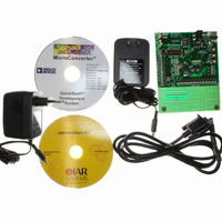
KIT DEV QUICK START FOR ADUC847
Manufacturer
Analog Devices Inc
Series
QuickStart™ Kitr
Type
MCUr
Datasheet
1.EVAL-ADUC845QSZ.pdf
(108 pages)
Specifications of EVAL-ADUC847QSZ
Contents
Evaluation Board, Power Supply, Cable, Software and Documentation
Silicon Manufacturer
Analog Devices
Core Architecture
8051
Silicon Core Number
ADuC847
Tool / Board Applications
General Purpose MCU, MPU, DSP, DSC
Mcu Supported Families
ADUC8xx
Development Tool Type
Hardware - Eval/Demo Board
Rohs Compliant
Yes
Lead Free Status / RoHS Status
Lead free / RoHS Compliant
For Use With/related Products
ADuC847
Lead Free Status / RoHS Status
Lead free / RoHS Compliant, Lead free / RoHS Compliant


WATCHDOG TIMER
The watchdog timer generates a device reset or interrupt within a
reasonable amount of time if the ADuC845/ADuC847/
ADuC848 enters an erroneous state, possibly due to a program-
ming error or electrical noise. The watchdog function can be
disabled by clearing the WDE (watchdog enable) bit in the
watchdog control (WDCON) SFR. When enabled, the
watchdog circuit generates a system reset or interrupt (WDS) if
the user program fails to set the WDE bit within a predetermined
amount of time (see the PRE3…0 bits in Table 44). The
Table 44. WDCON SFR Bit Designations
Bit No.
7, 6, 5, 4
3
2
1
0
Name
PRE3, PRE2, PRE1, PRE0
WDIR
WDS
WDE
WDWR
Description
Watchdog Timer Prescale Bits.
The watchdog timeout period is given by the equation
t
PRE3
0
0
0
0
0
0
0
0
1
PRE3–PRE0 > 1000b
Watchdog Interrupt Response Enable Bit.
If this bit is set by the user, the watchdog generates an interrupt response instead of a system reset
when the watchdog timeout period expires. This interrupt is not disabled by the CLR EA instruction,
and it is also a fixed, high priority interrupt. If the watchdog timer is not being used to monitor the
system, it can be used alternatively as a timer. The prescaler is used to set the timeout period in
which an interrupt is generated.
Watchdog Status Bit.
Set by the watchdog controller to indicate that a watchdog timeout has occurred.
Cleared by writing a 0 or by an external hardware reset. It is not cleared by a watchdog reset.
Watchdog Enable Bit.
Set by the user to enable the watchdog and clear its counters. If this bit is not set by the user within
the watchdog timeout period, the watchdog timer generates a reset or interrupt, depending on
WDIR.
Cleared under the following conditions: user writes 0; watchdog reset (WDIR = 0); hardware reset;
PSM interrupt.
Watchdog Write Enable Bit.
Writing data to the WDCON SFR involves a double instruction sequence. Global interrupts must first
be disabled. The WDWR bit is set with the very next instruction, a write to the WDCON SFR. For
example:
CLR EA
SETB WDWR
MOV WDCON, #72H
SETB EA
WD
= (2
PRE
PRE2
0
0
0
0
1
1
1
1
0
× (2
9
/ f
XTAL
PRE1
0
0
1
1
0
0
1
1
0
)) (0 ≤ PRE ≤ 7; f
Rev. B | Page 69 of 108
;Disable Interrupts while configuring to WDT
;Allow Write to WDCON
;Enable WDT for 2.0s timeout
;Enable Interrupts again (if required)
PRE0
0
1
0
1
0
1
0
1
0
watchdog timer is clocked from the 32 kHz external crystal
connected between the XTAL1 and XTAL2 pins. The WDCOM
SFR can be written only by user software if the double write
sequence described in WDWR is initiated on every write access
to the WDCON SFR.
WDCON—Watchdog Control Register
SFR Address:
Power-On Default:
Bit Addressable:
XTAL
Timeout Period (ms)
15.6
31.2
62.5
125
250
500
1000
2000
0.0
= 32.768 kHz)
ADuC845/ADuC847/ADuC848
C0H
10H
Yes
Action
Reset or interrupt
Reset or interrupt
Reset or interrupt
Reset or interrupt
Reset or interrupt
Reset or interrupt
Reset or interrupt
Reset or interrupt
Immediate reset
Reserved. Not a valid selection.
Related parts for EVAL-ADUC847QSZ
Image
Part Number
Description
Manufacturer
Datasheet
Request
R


Part Number:
Description:
BOARD EVAL FOR SI270X-A
Manufacturer:
Silicon Laboratories Inc
Datasheet:

Part Number:
Description:
BUCK CONV REF DESIGN KIT IP1201
Manufacturer:
International Rectifier
Datasheet:
Part Number:
Description:
BOARD DEMO SYNC DUAL BUCK CNVTER
Manufacturer:
International Rectifier
Datasheet:
Part Number:
Description:
BOARD DEMO SYNC BUCK CONVETER
Manufacturer:
International Rectifier
Datasheet:

Part Number:
Description:
EVALBOARD/EB Omnidirectional microphone - Analog
Manufacturer:
Analog Devices
Datasheet:
Part Number:
Description:
EVALBOARD/EB Omnidirectional microphone - Analog
Manufacturer:
Analog Devices
Datasheet:


Part Number:
Description:
BOARD EVAL LED DRIVER LT3756
Manufacturer:
Linear Technology
Datasheet:

Part Number:
Description:
BOARD EVAL FOR AD7741/7742
Manufacturer:
Analog Devices Inc
Datasheet:

Part Number:
Description:
±1.7g Dual-Axis IMEMS Accelerometer Evaluation Board
Manufacturer:
Analog Devices Inc
Datasheet:

Part Number:
Description:
IC MULTIPLIER ANALOG 8-SOIC T/R
Manufacturer:
Analog Devices Inc
Datasheet:

Part Number:
Description:
IC ANALOG MULTIPLIER 8-DIP
Manufacturer:
Analog Devices Inc
Datasheet:
Part Number:
Description:
IC ANALOG MULTIPLIER 8-SOIC
Manufacturer:
Analog Devices Inc
Datasheet:
Part Number:
Description:
IC ANALOG MULTIPLIER 8-DIP
Manufacturer:
Analog Devices Inc
Datasheet: