DEMO908QC16 Freescale Semiconductor, DEMO908QC16 Datasheet - Page 9
DEMO908QC16
Manufacturer Part Number
DEMO908QC16
Description
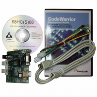
BOARD DEMO FOR MC908QC16
Manufacturer
Freescale Semiconductor
Type
MCUr
Specifications of DEMO908QC16
Contents
Board, Cable, CD
Processor To Be Evaluated
MC908QC16
Data Bus Width
8 bit
Interface Type
RS-232, USB
Silicon Manufacturer
Freescale
Core Architecture
HC08
Core Sub-architecture
HC08
Silicon Core Number
MC68HC908
Silicon Family Name
HC08Q
Kit Contents
Board
Rohs Compliant
No
For Use With/related Products
MC908QC16
Lead Free Status / RoHS Status
Contains lead / RoHS non-compliant


D E M O 9 0 8 Q C 1 6
ment Studio™ for HC(S)08 and the Axiom MON08 IDE for Windows. Both tool sets support
Debugging and Flash programming on the DEMO908QC16.
DEVELOPMENT SUPPORT
Application development and debug for the target MC68HC908QC16 is supported through the
MON08 Debug interface. The debug interface consists of an integrated USB-MON08 debug-
ger or an optional 16-pin MON08header. The MON08 header is not installed in default con-
figuration but may be installed by the user if necessary. Note that when using an external
MON08 cable, all jumpers on the USB-MON08 ENABLE header should be removed.
Integrated MON08
The DEMO908QC16 board features an integrated USB-MON08 debugger from P&E Micro-
computer Systems. The integrated debugger supports application development and debug-
ging via the internal monitor. All necessary signals, including high-voltage, clock, data, and
configuration signals, are provided by the integrated debugger. A USB, type B connector al-
lows connecting the target board to the host PC.
The integrated debugger provides +5V power and ground to target board eliminating the need
to power the board externally. Power from the USB-MON08 is derived from the USB bus;
therefore, total current consumption for the target board, and connected circuitry, must not ex-
ceed 500mA. Excessive current drain will violate the USB specification and will cause the
USB bus to disconnect. Damage to the host PC USB hub or the target board may result.
Option Header
A 16-pin header (USB-MON08 ENABLE) allows the user to disconnect the integrated debug-
ger from the target board. This allows the stand-alone operation of the target board. In stand-
alone operation, the target board must be power from connector J1 or the PWR connector.
To use the board in stand-alone operation when powered from the USB cable, remove shunts
at position “B” and “I”. The shunt at position “J” must remain on to supply power to the board.
The other shunt positions are “Don’t Care”.
Table 4: USB-MON08 Enable Header
F
E
D
C
B
J
I
14
12
10
8
6
4
2
13
11
9
7
5
3
1
Jumper On
Enabled
Enabled
Enabled
Enabled
Enabled
Enabled
Enabled
Jumper Off
Disabled
Disabled
Disabled
Disabled
Disabled
Disabled
Disabled
9
Signal
VB (+V out)
PTA3/RST*
PTA1/T1CH1
PTA4/OSC2
PTA0/T1CH0
PTA5/OSC1
PTA2/IRQ*
J U N E
2 0 ,
2 0 0 5
Related parts for DEMO908QC16
Image
Part Number
Description
Manufacturer
Datasheet
Request
R

Part Number:
Description:
Manufacturer:
STMicroelectronics
Datasheet:

Part Number:
Description:
DEMO BOARD FOR HMC6042/HMC1041Z
Manufacturer:
Honeywell Microelectronics & Precision Sensors

Part Number:
Description:
DEMO BOARD FOR HMC1042L/HMC1041Z
Manufacturer:
Honeywell Microelectronics & Precision Sensors
Datasheet:

Part Number:
Description:
KIT DEMO 4 SENSOR CHAN RS232
Manufacturer:
VTI Technologies
Datasheet:


Part Number:
Description:
DEMO: DC Power Supply, 32 Volts, 3 Amps
Manufacturer:
Tektronix
Part Number:
Description:
DEMO: Programmable DC Power Supply, 32 Volts, 3 Amps
Manufacturer:
Tektronix

Part Number:
Description:
Manufacturer:
Freescale Semiconductor, Inc
Datasheet:
Part Number:
Description:
Manufacturer:
Freescale Semiconductor, Inc
Datasheet:
Part Number:
Description:
Manufacturer:
Freescale Semiconductor, Inc
Datasheet:
Part Number:
Description:
Manufacturer:
Freescale Semiconductor, Inc
Datasheet:
Part Number:
Description:
Manufacturer:
Freescale Semiconductor, Inc
Datasheet:
Part Number:
Description:
Manufacturer:
Freescale Semiconductor, Inc
Datasheet:
Part Number:
Description:
Manufacturer:
Freescale Semiconductor, Inc
Datasheet:
Part Number:
Description:
Manufacturer:
Freescale Semiconductor, Inc
Datasheet: