DEMO9S08JS16 Freescale Semiconductor, DEMO9S08JS16 Datasheet - Page 9
DEMO9S08JS16
Manufacturer Part Number
DEMO9S08JS16
Description
BOARD DEMO FOR JS16 FAMILY
Manufacturer
Freescale Semiconductor
Type
MCUr
Datasheets
1.DC9S08JS16.pdf
(49 pages)
2.DEMO9S08JS16.pdf
(32 pages)
3.DEMO9S08JS16.pdf
(8 pages)
4.DEMO9S08JS16.pdf
(8 pages)
5.DEMO9S08JS16.pdf
(4 pages)
Specifications of DEMO9S08JS16
Contents
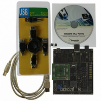
2 Boards, Cable, Documentation, DVD
Processor To Be Evaluated
MC9S08JS16
Data Bus Width
8 bit
Interface Type
USB
Operating Supply Voltage
5 V
Silicon Manufacturer
Freescale
Core Architecture
HCS08
Core Sub-architecture
HCS08
Silicon Core Number
MC9S08
Silicon Family Name
S08JS
Rohs Compliant
Yes
For Use With/related Products
MC9S08JS16
Lead Free Status / RoHS Status
Lead free / RoHS Compliant


2.4
2.5
DEMO9S08JS16 User Manual
Note:
DEMO9S08JS16 Daughter Card Features
DEMOJM Board Jumper/Connector Quick Reference
on the accompanying DVD-ROM, is a generic serial port utility which works
with the DEMOJM virtual serial port or actual serial port hardware.
Default Jumper Settings
The following is a list of default jumper settings for DEMOJM board. The
settings listed indicate the “on” (or installed) position.
The JS16 can only support USB device mode.
J13: PTA5 is used as GPIO.
J14: PTA4 is used as GPIO.
J21: JS16 has no ADC module.
J31: JS16 has no IIC module.
•
•
•
Four (4) bottom-mounted asymmetrically positioned 8x2 female
connectors to mate with the DEMOJM Base Board
A top-mounted MC9S08JS16CFK chip
Signals are mapped to the different modules to demonstrate different
functions:
•
•
•
•
•
TxD (PTA7) and RxD (PTA6) are mapped to TxD1 (PTE0) and
RxD1 (PTE1) of the DEMOJM 64Pin header
TPMCH0 (PTA0) and TPMCH1 (PTA5) are mapped to TPM1CH0
(PTE2) and TPM1CH1 (PTE3) on the DEMOJM 64Pin header
SPI Signals are mapped to SPI1 Signals on the DEMOJM 64 Pin
header
BLMS (PTB3) is mapped to PTG0 (KBIP0) of the DEMOJM 64Pin
header
KBIP1 (PTA1), KBIP6 (PTA6) and KBIP7 (PTA7) are mapped to
PTG1/PTG2/PTG3 correspondingly
5
Related parts for DEMO9S08JS16
Image
Part Number
Description
Manufacturer
Datasheet
Request
R

Part Number:
Description:
Manufacturer:
Freescale Semiconductor, Inc
Datasheet:
Part Number:
Description:
Manufacturer:
Freescale Semiconductor, Inc
Datasheet:
Part Number:
Description:
Manufacturer:
Freescale Semiconductor, Inc
Datasheet:
Part Number:
Description:
Manufacturer:
Freescale Semiconductor, Inc
Datasheet:
Part Number:
Description:
Manufacturer:
Freescale Semiconductor, Inc
Datasheet:
Part Number:
Description:
Manufacturer:
Freescale Semiconductor, Inc
Datasheet:
Part Number:
Description:
Manufacturer:
Freescale Semiconductor, Inc
Datasheet:
Part Number:
Description:
Manufacturer:
Freescale Semiconductor, Inc
Datasheet:
Part Number:
Description:
Manufacturer:
Freescale Semiconductor, Inc
Datasheet:
Part Number:
Description:
Manufacturer:
Freescale Semiconductor, Inc
Datasheet:
Part Number:
Description:
Manufacturer:
Freescale Semiconductor, Inc
Datasheet:
Part Number:
Description:
Manufacturer:
Freescale Semiconductor, Inc
Datasheet:
Part Number:
Description:
Manufacturer:
Freescale Semiconductor, Inc
Datasheet:
Part Number:
Description:
Manufacturer:
Freescale Semiconductor, Inc
Datasheet:
Part Number:
Description:
Manufacturer:
Freescale Semiconductor, Inc
Datasheet: