C8051F800DK Silicon Laboratories Inc, C8051F800DK Datasheet - Page 8
C8051F800DK
Manufacturer Part Number
C8051F800DK
Description
KIT DEV C8051F800
Manufacturer
Silicon Laboratories Inc
Type
MCUr
Specifications of C8051F800DK
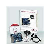
Contents
Board, Cables, CD, Debugger, Power Supply
Processor To Be Evaluated
C8051F800
Data Bus Width
16 bit
Interface Type
USB
Operating Supply Voltage
7 V to 15 V
Lead Free Status / RoHS Status
Contains lead / RoHS non-compliant
For Use With/related Products
C8051F8xx
Lead Free Status / Rohs Status
Supplier Unconfirmed
Other names
336-1797


C8051F800-DK
6. Example Source Code
Example source code and register definition files are provided in the “SiLabs\MCU\Examples\C8051F80x_83x\”
default directory during IDE installation. These files may be used as a template for code development. The
comments in each example file indicate which development tool chains were used when testing. Example
applications include a blinking LED example which configures the green LED on the target board to blink at a fixed
rate. Also included are examples for each of peripherals of the MCU such as the UART.
6.1. Register Definition Files
Register definition files C8051F800.inc, C8051F800_defs.h and compiler_defs.h define all SFR registers and bit-
addressable
“SiLabs\MCU\Examples\C8051F80x_83x\Header_Files\” default directory during IDE installation. The register and
bit names are identical to those used in the C8051F80x-83x data sheet.
6.2. Blinking LED Example
The
“SiLabs\MCU\Examples\C8051F80x_83x\Blinky” show examples of several basic C8051F800 functions. These
include disabling the watchdog timer (WDT), configuring the Port I/O crossbar, configuring a timer for an interrupt
routine, initializing the system clock, and configuring a GPIO port pin. When compiled/assembled and linked, this
program flashes the green LED on the C8051F800 Target Board about five times a second using the interrupt
handler with a C8051F800 timer.
6.3. Capacitive Sense Switch Example
The example source file F80x_CS0.c demonstrates the configuration and usage of the capacitive sense switches
labeled P1.5 and P1.6. Refer to the source file for step-by-step instructions to build and test this example. This is
installed in the “SiLabs\MCU\Examples\C8051F80x_83x\CS0” directory by default.
6.4. QuickSense
The QuickSense Studio software install (available at www.silabs.com/quicksense) includes a QuickSense Firm-
ware API example for the C8051F800 Target Board. This is installed in the “SiLabs\MCU\QuickSense_Studio\Firm-
ware\F800_TargetBoard” directory by default. In addition to the source files, a pre-built Intel Hex file (F800TB.hex)
is also included for quick evaluation. This firmware uses the QuickSense Firmware API to measure capacitance on
the two sensing pads and application layer code indicates touch using the LEDs on the board. The firmware pro-
vides the following functionality:
For a more detailed description of the QuickSense Firmware API or the Serial Interface, see “AN366: QuickSense
API.” For a more detailed description of active/inactive thresholds, see “AN367: Understanding Capacitive Sensing
Signal to Noise Ratios.” For a discussion on baselining in the QuickSense Firmware API, see “AN418: Baselining
in the QuickSense Firmware API.
8
When the capacitive sense button labeled P1.5 is touched, the four LEDs labeled P1.0 through P1.3 are
sequentially lit from bottom to top.
When the capacitive sense button labeled P1.6 is touched, the four LEDs are sequentially lit from top to bottom.
When both the buttons P1.5 and P1.6 are touched simultaneously, the LED sequencing is paused.
When neither of the two buttons is touched, all the four LEDs are not lit.
example
source
control/status
TM
Firmware API Example
files
F800_Blinky.asm
bits.
These
and
Rev. 0.1
F800_Blinky.c
files
are
installed
installed
in
the
default
into
directory
the
Related parts for C8051F800DK
Image
Part Number
Description
Manufacturer
Datasheet
Request
R

Part Number:
Description:
SMD/C°/SINGLE-ENDED OUTPUT SILICON OSCILLATOR
Manufacturer:
Silicon Laboratories Inc
Part Number:
Description:
Manufacturer:
Silicon Laboratories Inc
Datasheet:
Part Number:
Description:
N/A N/A/SI4010 AES KEYFOB DEMO WITH LCD RX
Manufacturer:
Silicon Laboratories Inc
Datasheet:
Part Number:
Description:
N/A N/A/SI4010 SIMPLIFIED KEY FOB DEMO WITH LED RX
Manufacturer:
Silicon Laboratories Inc
Datasheet:
Part Number:
Description:
N/A/-40 TO 85 OC/EZLINK MODULE; F930/4432 HIGH BAND (REV E/B1)
Manufacturer:
Silicon Laboratories Inc
Part Number:
Description:
EZLink Module; F930/4432 Low Band (rev e/B1)
Manufacturer:
Silicon Laboratories Inc
Part Number:
Description:
I°/4460 10 DBM RADIO TEST CARD 434 MHZ
Manufacturer:
Silicon Laboratories Inc
Part Number:
Description:
I°/4461 14 DBM RADIO TEST CARD 868 MHZ
Manufacturer:
Silicon Laboratories Inc
Part Number:
Description:
I°/4463 20 DBM RFSWITCH RADIO TEST CARD 460 MHZ
Manufacturer:
Silicon Laboratories Inc
Part Number:
Description:
I°/4463 20 DBM RADIO TEST CARD 868 MHZ
Manufacturer:
Silicon Laboratories Inc
Part Number:
Description:
I°/4463 27 DBM RADIO TEST CARD 868 MHZ
Manufacturer:
Silicon Laboratories Inc
Part Number:
Description:
I°/4463 SKYWORKS 30 DBM RADIO TEST CARD 915 MHZ
Manufacturer:
Silicon Laboratories Inc
Part Number:
Description:
N/A N/A/-40 TO 85 OC/4463 RFMD 30 DBM RADIO TEST CARD 915 MHZ
Manufacturer:
Silicon Laboratories Inc
Part Number:
Description:
I°/4463 20 DBM RADIO TEST CARD 169 MHZ
Manufacturer:
Silicon Laboratories Inc