MPC8313E-RDBB Freescale Semiconductor, MPC8313E-RDBB Datasheet - Page 15
MPC8313E-RDBB
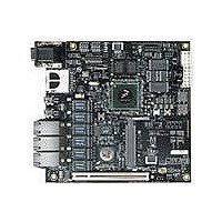
Manufacturer Part Number
MPC8313E-RDBB
Description
BOARD CPU 8313E VER 2.1
Manufacturer
Freescale Semiconductor
Series
PowerQUICC II™ PROr
Type
MPUr
Datasheets
1.MPC8313CZQAFFB.pdf
(100 pages)
2.MPC8313E-RDBB.pdf
(52 pages)
3.MPC8313E-RDBB.pdf
(2 pages)
Specifications of MPC8313E-RDBB
Contents
Board
Processor To Be Evaluated
MPC8xxx
Data Bus Width
32 bit
Interface Type
Ethernet, USB, JTAG, SPI, UART
Dimensions
170 mm x 170 mm
Operating Supply Voltage
3.3 V
For Use With/related Products
MPC8313E
Lead Free Status / RoHS Status
Lead free / RoHS Compliant


the reset configuration word value in I
reference manual.
2.7
An SD memory card interface connects directly to the SPI bus of the MPC8313E. SD data mode and SDIO
mode are not supported. The SPI mode is the only SD operating mode supported by this connection. Hot
insertion and removal is not supported. See
For REVB boards, the SD card chip select signal is changed from GPIO31(SPISEL) to GPIO13(LA8)
because when using SPI as master mode, SPISEL cannot be set as GPIO (which is supposed to be used for
device select signal). In this case, another GPIO pin should be used. GPIO13 is implemented on this board
as an example.
Freescale Semiconductor
SD Memory Card Interface
MPC8313E
PowerQUICC™ MPC8313E Reference Design Board (RDB), Rev. 4
I2C1-SDA
I2C1-SCL
2
C EEPROM and the boot sequencer mode, refer to the MPC8313E
Figure 11. I
3.3 V
Figure 12
2
C Connection
for the hardware connection.
I
2
SDA
I
SCL
I
SDA
I
SDA
SCL
SDA
I
C DAC (Optional)
SCL
2
SCL
2
2
2
C Address = 0x50
C Address = 0x0C
I
C Address = 0x68
C Address = 0x48
2
I
DS1339U
2
C EEROM
M24256
I
AD5301
C Sensor
2
LM75
C RTC
Board-Level Functions
15
Related parts for MPC8313E-RDBB
Image
Part Number
Description
Manufacturer
Datasheet
Request
R

Part Number:
Description:
Mpc8313e Powerquicc Ii Pro Processor
Manufacturer:
Freescale Semiconductor, Inc
Datasheet:

Part Number:
Description:
BOARD PROCESSOR
Manufacturer:
Freescale Semiconductor
Datasheet:

Part Number:
Description:
BOARD CPU 8313E VER 2.2
Manufacturer:
Freescale Semiconductor
Datasheet:
Part Number:
Description:
Microprocessors - MPU 8313 REV2.2 PB ENC EXT
Manufacturer:
Freescale Semiconductor
Datasheet:
Part Number:
Description:
Microprocessors - MPU 8313 REV2.2 PB W/ENC
Manufacturer:
Freescale Semiconductor
Datasheet:
Part Number:
Description:
Microprocessors - MPU 8313 REV2.2 PB NO EN EXT
Manufacturer:
Freescale Semiconductor
Datasheet:
Part Number:
Description:
Microprocessors - MPU 8313 REV2.2 PB NO ENC
Manufacturer:
Freescale Semiconductor
Datasheet:
Part Number:
Description:
Manufacturer:
Freescale Semiconductor, Inc
Datasheet:
Part Number:
Description:
Manufacturer:
Freescale Semiconductor, Inc
Datasheet:
Part Number:
Description:
Manufacturer:
Freescale Semiconductor, Inc
Datasheet:
Part Number:
Description:
Manufacturer:
Freescale Semiconductor, Inc
Datasheet:
Part Number:
Description:
Manufacturer:
Freescale Semiconductor, Inc
Datasheet:
Part Number:
Description:
Manufacturer:
Freescale Semiconductor, Inc
Datasheet:
Part Number:
Description:
Manufacturer:
Freescale Semiconductor, Inc
Datasheet:
Part Number:
Description:
Manufacturer:
Freescale Semiconductor, Inc
Datasheet: