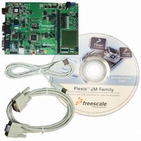
EVB51JM128 Freescale Semiconductor, EVB51JM128 Datasheet

EVB51JM128
Specifications of EVB51JM128
Related parts for EVB51JM128
EVB51JM128 Summary of contents
Page 1
... Development Board for Freescale MCF51JM128 MCU EVB51JM128 Hardware User Guide Support: Email: www.axman.com support@axman.com ...
Page 2
CAUTIONARY NOTES ..............................................................................................................4 TERMINOLOGY.........................................................................................................................4 FEATURES ................................................................................................................................5 REFERENCES ...........................................................................................................................6 GETTING STARTED..................................................................................................................6 APPLICATION DEVELOPMENT ...............................................................................................6 HARDWARE CONFIGURATION ...............................................................................................6 INTEGRATED BDM............................................................................................................... 6 BDM PORT ...
Page 3
LCD PORT CONNECTORS ............................................................................................ 16 LCD ENABLE .................................................................................................................. 16 USB CONTROLLER ................................................................................................................17 ACCELEROMETER .................................................................................................................18 ACCELEROMETER CONFIGURATION ............................................................................. 18 MCU_PORT ........................................................................................................................ 20 ...
Page 4
Date December 11, 2007 February 1, 2008 REVISION Rev Comments A Initial Release. B Added accel notes, updated LED8 jumper configura- ...
Page 5
... EMC Information on the EVB51JM128 board: a) This product, as shipped from the factory with associated power supplies and cables, has been verified to meet with FCC requirements as a CLASS A product. ...
Page 6
... FEATURES The EVB51JM128 is a low-cost development system for the Freescale MCF51JM128 ColdFire microcontroller, which is a part of the Freescale FLEXIS Microcontroller Continuum. CodeWar- rior Development Tools provide support for quick and easy application development and de- bug. A BDM port compatible with standard ColdFire BDM / JTAG interface cables and hosting software is provided for programming and debug support ...
Page 7
... EVB51JM12_QSG.pdf EVB51JM128_SCH_B.pdf EVB51JM128_Silk_A.pdf GETTING STARTED To get started quickly, please refer to the EVB51JM128 Quick Start Guide. This quick start will illustrate connecting the board to a PC, installing the correct version of CodeWarrior Develop- ment Studio, and run a simple demo program. APPLICATION DEVELOPMENT CodeWarrior Development Studio for ColdFire, Special Edition is provided along with the EVB51JM128 to support application development and debug ...
Page 8
... BKGD*/MS 1 EVB POWER The EVB51JM128 applies 2 voltage regulators to power the board. VR1 supplies +5V to the VDD rail when selected. This regulator also provide +5V output to the USB circuitry when the board is configured for HOST mode. VR2 supplies +3.3V to the VDD rail when selected. The +3 ...
Page 9
The terminal block, TB1, allows the user to apply an alternate power source to the board. In- put voltage, +VIN, should ...
Page 10
Figure 4: PWR_SEL Option Header PWR_SEL • • • BDM VR1 PWR_SEL • • • BDM VR1 MCU Power Each power ...
Page 11
VREFL Option Header The VREFL option header connects the target device VREFL input to the EVB digital ground by default. This ...
Page 12
... SRAM memory. Refer to the MCF51JM128RM for details on memory type and location. TIMING The EVB51JM128 accepts timing input from several sources MHz crystal is provided to support application development. The target device also provides an internal timing source with 9-bit trimming. Locations for a vertical SMA connector and a 14-pos DIP socket are pro- vided but not installed in default configurations ...
Page 13
... PLL settings are under user application control and may be changed during application execu- tion. Communications The EVB51JM128 board provides 2 UART ports, 1 IIC port, and 1 USB OTG port. RS-232 communication is supported through UART[2:0] connectors and through the MCU_PORT con- nector. IIC communications are supported solely through the MCU_PORT connector. The COM_EN option header enables SCI functionality between the MCU and the associated UARTx connector ...
Page 14
... GND CAN Communications The EVB51JM128 provides a high-speed CAN physical layer interface (PHY). A 3-pin con- nector provides connectivity to the off-board CAN bus. The CAN PHY connects to the CAN0 channel on the MCU. The PHY supports data rates MBPS with edge-rate control to reduce EMI/RFI. The figure below shows the pin-out of the CAN_PORT connector. ...
Page 15
User Pushbutton Switches Four user push-button switches are provided for user application input as needed and are con- figured for active-low ...
Page 16
Table 4: POT POT PTB2/SPSCK2/ADP2 PTD1/ADP9/ACMP- Light Sensor A surface-mount phototransistor, at RZ1, provides light sensitive, variable input for user appli- ...
Page 17
... IR Diode PTC2/IRO LCD PORT The EVB51JM128 applies an LCD port with adjustable contrast input. The LCD port is de- signed to support the CM082B-SGR1-Z LCD from FEMA Electronics. A 2x7 socket header must be installed on the LCD module for connection to the LCD port. The LCD port supports a 2x20, STN type, reflective, character LCD panel. LCD panel contract is adjustable using the CONTRAST pot ...
Page 18
... PTE6/SPSCK1 • • PTE4/MISO1 USB CONTROLLER The EVB51JM128 provides an on-board USB physical layer interface (PHY) capable of Host mode, Device mode, and On-the-Go (OTG) mode applications. A Type-A USB connector supports Host mode connections. A miniAB connector supports OTG applications. An op- tional 6-in-1 USB cable supports Device mode applications. The output USB signal lines (USBP, USBN) are biased either manually or under program control ...
Page 19
... Refer to the ADM869L datasheet for details on the operation of the hi-side switch. ACCELEROMETER The EVB51JM128 applies an MMA7260Q, 3-axis accelerometer for tilt and motion-sense ap- plications. The accelerometer supports 4 user selectable sensitivities - 1. 6g. The SLEEP* input allows the device to be placed in a low-power mode. Separate X-, Y-, and Z- axis readings are routed to the MCU ...
Page 20
option header at ACC_OUT allows the user to disconnect the accelerometer output if nec- essary. Table 12: ACC_OUT Option Header ...
Page 21
MCU_PORT The MCU PORT provides user access to the MCF51JM128 I/O ports. MCF51JM128 Integrated Device Reference Manual for signal details. Figure ...
Page 22
NOTE: Only primary signal name is applied to MCU_PORT silkscreen ...
Page 23
... TROUBLESHOOTING The EVB51JM128 is fully tested and operational before shipping fails to function properly, inspect the board for obvious physical damage first. Verify the communications setup as de- scribed under GETTING STARTED. Most common problems are related to improperly configured options or communications pa- rameters. 1. Verify the +3.3V and +5V voltage indicators are ON. ...


