EVB51JM128 Freescale Semiconductor, EVB51JM128 Datasheet - Page 17
EVB51JM128
Manufacturer Part Number
EVB51JM128
Description
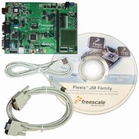
BOARD EVAL FOR MCF51JM128 MCU
Manufacturer
Freescale Semiconductor
Series
ColdFire®r
Type
MCUr
Datasheets
1.EVB51JM128.pdf
(23 pages)
2.EVB51JM128.pdf
(2 pages)
3.EVB51JM128.pdf
(3 pages)
4.EVB51JM128.pdf
(4 pages)
Specifications of EVB51JM128
Contents
Evaluation Board
Silicon Manufacturer
Freescale
Core Architecture
Coldfire
Core Sub-architecture
Coldfire V1
Silicon Core Number
MCF51J
Silicon Family Name
Flexis - MCF51JM
Rohs Compliant
Yes
For Use With/related Products
MCF51JM128
Lead Free Status / RoHS Status
Lead free / RoHS Compliant


E V B 5 1 J M 1 2 8
Table 8: Push Button Switches
LCD PORT
The EVB51JM128 applies an LCD port with adjustable contrast input. The LCD port is de-
signed to support the CM082B-SGR1-Z LCD from FEMA Electronics. A 2x7 socket header
must be installed on the LCD module for connection to the LCD port.
The LCD port supports a 2x20, STN type, reflective, character LCD panel. LCD panel contract
is adjustable using the CONTRAST pot. The LCD setup does not support current cursor posi-
tion read-back.
The LCD port is connected to serial peripheral interface port #1 on the target MCU. A shift
data to a parallel format required by the LCD.
LCD Port Connectors
The LCD control and data signals are connected directly to the MCU_PORT I/O headers. The
signal arrangement is designed to coincide with the SPI port of a line of plug-in modules de-
signed by Axiom Manufacturing. To provide maximum flexibility, the select signal SS* has
been connected to both a dedicated SS* output and to a GPIO signal on the MCU module. An
option header at SS*, selects the select signal source. An option header at LCD_EN also al-
lows the user to disconnect the LCD module from the MCU_PORT signal lines. To prevent
signal corruption when using the SPI signals as general purpose I/O, the user should remove
the shunts on LCD_EN and SS* option headers.
Figure 10: LCD_PORT – J13
LCD Enable
CONTRAST
NOTE: The LCD module must be connected directly to the LCD port. If a cable is used to
IR Diode
LCD_D4
LCD_D6
R/W*
GND
DB0
DB2
connect the LCD module, ensure the VDD and GND inputs are not reversed.
U S E R
11
13
1
3
5
7
9
PTC2/IRO
G U I D E
10
12
14
2
4
6
8
VDD
RS
EN
DB1
DB3
LCD_D5
LCD_D7
SPI data bit definitions to LCD Port:
LCD_D[7..4] – LCD data bits D[3..0]
DB[3..0] – Unused, 10K ohm pull-downs installed
R/W – Read/Write pin, set to 0 volts, Read only
EN – LCD enable input, 1 = LCD enable
CONTRAST – LCD contrast input
RS – Register Select, 0 = LCD Command, 1 = LCD Data
16
F E B R U A R Y
1 ,
2 0 0 8
Related parts for EVB51JM128
Image
Part Number
Description
Manufacturer
Datasheet
Request
R

Part Number:
Description:
Manufacturer:
Freescale Semiconductor, Inc
Datasheet:
Part Number:
Description:
Manufacturer:
Freescale Semiconductor, Inc
Datasheet:
Part Number:
Description:
Manufacturer:
Freescale Semiconductor, Inc
Datasheet:
Part Number:
Description:
Manufacturer:
Freescale Semiconductor, Inc
Datasheet:
Part Number:
Description:
Manufacturer:
Freescale Semiconductor, Inc
Datasheet:
Part Number:
Description:
Manufacturer:
Freescale Semiconductor, Inc
Datasheet:
Part Number:
Description:
Manufacturer:
Freescale Semiconductor, Inc
Datasheet:
Part Number:
Description:
Manufacturer:
Freescale Semiconductor, Inc
Datasheet:
Part Number:
Description:
Manufacturer:
Freescale Semiconductor, Inc
Datasheet:
Part Number:
Description:
Manufacturer:
Freescale Semiconductor, Inc
Datasheet:
Part Number:
Description:
Manufacturer:
Freescale Semiconductor, Inc
Datasheet:
Part Number:
Description:
Manufacturer:
Freescale Semiconductor, Inc
Datasheet:
Part Number:
Description:
Manufacturer:
Freescale Semiconductor, Inc
Datasheet:
Part Number:
Description:
Manufacturer:
Freescale Semiconductor, Inc
Datasheet:
Part Number:
Description:
Manufacturer:
Freescale Semiconductor, Inc
Datasheet: