TOOLSTICK311DC Silicon Laboratories Inc, TOOLSTICK311DC Datasheet - Page 13
TOOLSTICK311DC
Manufacturer Part Number
TOOLSTICK311DC
Description
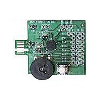
TOOLSTICK DAUGHTER CARD
Manufacturer
Silicon Laboratories Inc
Series
ToolStickr
Type
MCUr
Datasheet
1.TOOLSTICK311DC.pdf
(16 pages)
Specifications of TOOLSTICK311DC
Contents
Daughter Card
Processor To Be Evaluated
C8051F311
Interface Type
USB
Operating Supply Voltage
2.7 V to 3.6 V
Lead Free Status / RoHS Status
Lead free / RoHS Compliant
For Use With/related Products
C8051F311
Lead Free Status / Rohs Status
Lead free / RoHS Compliant


7. Using the C8051F311 Daughter Card as a Development Platform
The prototyping area on the ToolStick C8051F311 daughter card makes it easy to interface to external hardware.
All of the digital I/O pins are available so it possible to create a complete system.
7.1. C8051F311 Pin Connections
It is important to note that if external hardware is being added, some of the existing components on the board can
interfere with the signaling. The following is a list of port pins on the C8051F311 that are connected to other
components:
7.2. C2 Pin Sharing
On the C8051F311, the debug pins, C2CK, and C2D, are shared with the pins /RST and P0.7 respectively. The
daughter card includes the resistors necessary to enable pin sharing which allow the /RST and P0.7 pins to be
used normally while simultaneously debugging the device. See "AN124: Pin Sharing Techniques for the C2
Interface" at www.silabs.com for more information regarding pin sharing.
8. Information Locations
Example source code is installed by default in the C:\SiLabs\MCU\ToolStick\F311DC\Firmware directory during the
ToolStick installation.
Documentation for the ToolStick kit, including this User's Guide, can be found by default in the
C:\SiLabs\MCU\ToolStick\Documentation and the C:\SiLabs\MCU\ToolStick\F311DC\Documentation directories.
The installer for the ToolStick software is available at www.silabs.com/toolstick.
P0.1, P0.6-These pins are connected directly to the ToolStick Base Adapter's GPIO pins. By default, these
GPIO pins on the Base Adapter are high-impedance pins so they will not affect any signaling. Configuring these
pins on the Base Adapter to output pin or handshaking pins could affect signaling.
P0.4, P0.5-These pins are connected directly to the ToolStick Base Adapter for UART communication.
P0.7-This pin is connected to the "S1" switch. The switch can be removed to disconnect them from the pin.
P1.0-This pin is connected to the cathode of the green LED on the daughter card. The LED or the R2 resistor
can be removed to disconnect the LED from the pin.
P1.2-This pin is connected to the output of the potentiometer. R5 (a 0 Ω resistor) can be removed to disconnect
the potentiometer from the pin.
See “9. C8051F311 Daughter Card Schematic” for more information.
Rev. 0.1
ToolStick-F311DC
13
Related parts for TOOLSTICK311DC
Image
Part Number
Description
Manufacturer
Datasheet
Request
R

Part Number:
Description:
KIT TOOL EVAL SYS IN A USB STICK
Manufacturer:
Silicon Laboratories Inc
Datasheet:

Part Number:
Description:
TOOLSTICK DEBUG ADAPTER
Manufacturer:
Silicon Laboratories Inc
Datasheet:

Part Number:
Description:
TOOLSTICK BASE ADAPTER
Manufacturer:
Silicon Laboratories Inc
Datasheet:

Part Number:
Description:
TOOLSTICK DAUGHTER CARD
Manufacturer:
Silicon Laboratories Inc
Datasheet:

Part Number:
Description:
TOOLSTICK DAUGHTER CARD
Manufacturer:
Silicon Laboratories Inc
Datasheet:

Part Number:
Description:
TOOLSTICK PROGRAMMING ADAPTER
Manufacturer:
Silicon Laboratories Inc
Datasheet:

Part Number:
Description:
TOOLSTICK DAUGHTER CARD
Manufacturer:
Silicon Laboratories Inc
Datasheet:

Part Number:
Description:
KIT STARTER TOOLSTICK
Manufacturer:
Silicon Laboratories Inc
Datasheet:

Part Number:
Description:
KIT UNIVERSITY TOOLSTICK STARTER
Manufacturer:
Silicon Laboratories Inc
Datasheet:

Part Number:
Description:
DAUGHTER CARD TOOLSTICK F330
Manufacturer:
Silicon Laboratories Inc
Datasheet:

Part Number:
Description:
CARD DAUGHTER UNIVRSTY TOOLSTICK
Manufacturer:
Silicon Laboratories Inc
Datasheet:

Part Number:
Description:
DAUGHTER CARD TOOLSTICK F582
Manufacturer:
Silicon Laboratories Inc
Datasheet:

Part Number:
Description:
DAUGHTER CARD TOOLSTICK F500
Manufacturer:
Silicon Laboratories Inc
Datasheet:

Part Number:
Description:
DAUGHTER CARD TOOLSTICK F540
Manufacturer:
Silicon Laboratories Inc
Datasheet:

Part Number:
Description:
DAUGHTER CARD TOOLSTICK F560
Manufacturer:
Silicon Laboratories Inc
Datasheet: