C8051F930-TB Silicon Laboratories Inc, C8051F930-TB Datasheet - Page 21
C8051F930-TB
Manufacturer Part Number
C8051F930-TB
Description
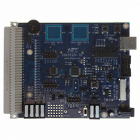
BOARD TARGET/PROTO W/C8051F930
Manufacturer
Silicon Laboratories Inc
Type
MCUr
Specifications of C8051F930-TB
Contents
Board
Processor To Be Evaluated
C8051F930
Processor Series
C8051F9xx
Data Bus Width
8 bit
Interface Type
I2C, UART, SPI
Maximum Operating Temperature
+ 85 C
Minimum Operating Temperature
- 40 C
Operating Supply Voltage
0.9 V to 3.6 V
Lead Free Status / RoHS Status
Lead free / RoHS Compliant
For Use With/related Products
C8051F930
Lead Free Status / Rohs Status
Lead free / RoHS Compliant
Other names
336-1472


8. Frequently Asked Questions
1. Should power be turned off when switching between one-cell and two-cell mode?
2. I have placed the MCU in Sleep Mode. Why is the supply current greater than 1 µA?
3. I have been measuring the sleep mode current using the “µA” setting on my multimeter. Why am I no
4. Where can I find a schematic of the C8051F930 Target Board?
5. Which power LED should I use to determine if the MCU is powered?
Yes, power must be turned off by placing SW5 in the OFF position when switching between one-cell and two-
cell mode. Switching between modes while power is on may result in increased power consumption and
possible damage to low voltage transistors.
This can be caused by a number of factors. Check the following:
longer able to connect to the IDE?
When most multimeters are placed in “µA” mode, a large resistance is placed in series with the power supply.
This “current limiting” resistor prevents the MCU from starting up. To measure current during startup, make sure
that the multimeter is configured to its “mA” setting.
Alternatively, a shorting block can be placed on J17 to ensure that the multimeter does not limit current during
startup.
A target board schematic can be found in the C8051F930-DK User’s Guide which is available on the
Development Tools CD and is installed in the following folder (by default):
C:\SiLabs\MCU\Documentation\UsersGuides
The VDD/DC+ LED (DS5) should be used to determine if the MCU is powered. If you have applied power to the
board, but the VDD/DC+ LED is not turning on, check the following:
a. Verify that the USB Debug Adapter is not connected to the device. When connected, it can draw
b. Verify that the P1.5 and P1.6 LEDs are turned off in software (P1.5 and P1.6 set to logic HIGH).
c. Verify that the VDD/DC+ Power LED is disabled (remove shorting block from J5).
d. Verify that the shorting block on J15 does not connect the potentiometer negative terminal to GND, since
e. Verify that J7, J13, and J14 do not have shorting blocks installed.
a. Verify that the correct power source (J10, J11) is selected.
b. Verify that J17 has a shorting block.
c. Verify that SW5 is in the ON position.
d. Verify that J5 has a shorting block installed.
approximately 2–5 µA from the VDD/DC+ supply net.
Alternatively, the P1.5 and P1.6 LEDs can be disabled by removing the corresponding shorting blocks
from J8.
this would result in continuous current of ~ 300 µA. The shorting block may be removed, or configured to
enable the potentiometer when P1.4 is set to logic LOW. When the potentiometer enable is under
software control, be sure to set P1.4 to logic HIGH prior to placing the device in Sleep Mode.
Rev. 0.5
C8051F930-DK
21
Related parts for C8051F930-TB
Image
Part Number
Description
Manufacturer
Datasheet
Request
R

Part Number:
Description:
SMD/C°/SINGLE-ENDED OUTPUT SILICON OSCILLATOR
Manufacturer:
Silicon Laboratories Inc
Part Number:
Description:
Manufacturer:
Silicon Laboratories Inc
Datasheet:
Part Number:
Description:
N/A N/A/SI4010 AES KEYFOB DEMO WITH LCD RX
Manufacturer:
Silicon Laboratories Inc
Datasheet:
Part Number:
Description:
N/A N/A/SI4010 SIMPLIFIED KEY FOB DEMO WITH LED RX
Manufacturer:
Silicon Laboratories Inc
Datasheet:
Part Number:
Description:
N/A/-40 TO 85 OC/EZLINK MODULE; F930/4432 HIGH BAND (REV E/B1)
Manufacturer:
Silicon Laboratories Inc
Part Number:
Description:
EZLink Module; F930/4432 Low Band (rev e/B1)
Manufacturer:
Silicon Laboratories Inc
Part Number:
Description:
I°/4460 10 DBM RADIO TEST CARD 434 MHZ
Manufacturer:
Silicon Laboratories Inc
Part Number:
Description:
I°/4461 14 DBM RADIO TEST CARD 868 MHZ
Manufacturer:
Silicon Laboratories Inc
Part Number:
Description:
I°/4463 20 DBM RFSWITCH RADIO TEST CARD 460 MHZ
Manufacturer:
Silicon Laboratories Inc
Part Number:
Description:
I°/4463 20 DBM RADIO TEST CARD 868 MHZ
Manufacturer:
Silicon Laboratories Inc
Part Number:
Description:
I°/4463 27 DBM RADIO TEST CARD 868 MHZ
Manufacturer:
Silicon Laboratories Inc
Part Number:
Description:
I°/4463 SKYWORKS 30 DBM RADIO TEST CARD 915 MHZ
Manufacturer:
Silicon Laboratories Inc
Part Number:
Description:
N/A N/A/-40 TO 85 OC/4463 RFMD 30 DBM RADIO TEST CARD 915 MHZ
Manufacturer:
Silicon Laboratories Inc
Part Number:
Description:
I°/4463 20 DBM RADIO TEST CARD 169 MHZ
Manufacturer:
Silicon Laboratories Inc