AT91SAM9G45-EKES Atmel, AT91SAM9G45-EKES Datasheet - Page 11
AT91SAM9G45-EKES
Manufacturer Part Number
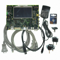
AT91SAM9G45-EKES
Description
KIT EVAL FOR AT91SAM9G45
Manufacturer
Atmel
Series
AT91SAM Smart ARMr
Type
MCUr
Datasheets
1.AT91SAM9G45-EKES.pdf
(56 pages)
2.AT91SAM9G45-EKES.pdf
(1218 pages)
3.AT91SAM9G45-EKES.pdf
(66 pages)
Specifications of AT91SAM9G45-EKES
Contents
Board
Processor To Be Evaluated
SAM9G45
Data Bus Width
32 bit
Interface Type
I2C, SPI, UART
Maximum Operating Temperature
+ 50 C
Minimum Operating Temperature
- 10 C
Operating Supply Voltage
1.8 V to 3.3 V
For Use With/related Products
AT91SAM9G45
Lead Free Status / RoHS Status
Lead free / RoHS Compliant
Other names
Q4626953


6481B–ATARM–27-Nov-09
Board Description
4.1.2
4.1.3
4-2
Board Interface Connection
Push Button Switches
One TWI serial memory
One USB Host/Device multiplexed port interface
One USB Host port interface
One RS232 serial communication port
One DBGU serial communication port
One JTAG/ICE debug interface
One Ethernet 100-base TX with three status LEDs
One AC97 Audio DAC with headphone line out, line in and mono/stereo micro inputs
One TV interface (composite video output)
One 4.3" TFT LCD Module with touch screen and back light
One ISI connector (camera interface)
One Power red LED and two general-purpose green LEDs
Two user input push buttons
One joystick with 4-direction control and selector
One Wakeup input push button
One reset input push button
One DataFlash®/SD/SDIO/MMC plus card slot (4/8 bit interface)
One SD/SDIO/MMC card slot (4-bit interface)
One Lithium Coin Cell Battery Retainer for 12 mm cell size (memory backup usage)
Ethernet using RJ45 connector (J15)
USB Host, support USB host using a type A connector (J12)
USB Host/Device, support USB host/device using a type micro AB connector (J14)
UART1 (Rx, Tx, Rts, Cts) connected to a 9-way male D-type RS232 connector (J11)
DBGU (Rx and Tx only) connected to a 9-way male D-type RS232 connector (J10)
JTAG, 20 pin IDC connector (J13)
SD/MMCplus connector (J5)
SD/MMC connector (J6)
Headphone (J7), line-in (J8) and microphone headset (J9)
Speaker output (JP15)
Image sensor connector (J17)
TFT LCD display (J16), with TouchScreen (J19) and BackLigth (J21)
Test points; various test points are located throughout the board
Main power supply (J2)
Reset, board reset (BP1)
Wake up, push button to bring processor out of low power mode (BP2)
Right and left click, user push button switches (BP4 and BP5)
Joystick (BP3)
AT91SAM9G45-EKES User Guide
Related parts for AT91SAM9G45-EKES
Image
Part Number
Description
Manufacturer
Datasheet
Request
R

Part Number:
Description:
MCU ARM9 64K SRAM 144-LFBGA
Manufacturer:
Atmel
Datasheet:

Part Number:
Description:
IC ARM7 MCU FLASH 256K 100LQFP
Manufacturer:
Atmel
Datasheet:

Part Number:
Description:
IC ARM9 MPU 217-LFBGA
Manufacturer:
Atmel
Datasheet:
Part Number:
Description:
MCU ARM9 ULTRA LOW PWR 217-LFBGA
Manufacturer:
Atmel
Datasheet:

Part Number:
Description:
MCU ARM9 324-TFBGA
Manufacturer:
Atmel
Datasheet:
Part Number:
Description:
IC MCU ARM9 SAMPLING 217CBGA
Manufacturer:
Atmel
Datasheet:
Part Number:
Description:
IC ARM9 MCU 217-LFBGA
Manufacturer:
Atmel
Datasheet:

Part Number:
Description:
IC ARM9 MCU 208-PQFP
Manufacturer:
Atmel
Datasheet:
Part Number:
Description:
MCU ARM 512K HS FLASH 100-LQFP
Manufacturer:
Atmel
Datasheet:

Part Number:
Description:
MCU ARM 512K HS FLASH 100-TFBGA
Manufacturer:
Atmel
Datasheet:
Part Number:
Description:
IC ARM9 MCU 200 MHZ 324-TFBGA
Manufacturer:
Atmel
Datasheet:

Part Number:
Description:
IC ARM MCU 16BIT 128K 256BGA
Manufacturer:
Atmel
Datasheet:

Part Number:
Description:
IC ARM7 MCU 32BIT 128K 64LQFP
Manufacturer:
Atmel
Datasheet:

Part Number:
Description:
IC ARM7 MCU FLASH 256K 128-LQFP
Manufacturer:
Atmel
Datasheet:
Part Number:
Description:
IC ARM7 MCU FLASH 512K 128-LQFP
Manufacturer:
Atmel
Datasheet: