AT91SAM9G45-EKES Atmel, AT91SAM9G45-EKES Datasheet - Page 12
AT91SAM9G45-EKES
Manufacturer Part Number
AT91SAM9G45-EKES
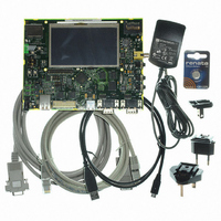
Description
KIT EVAL FOR AT91SAM9G45
Manufacturer
Atmel
Series
AT91SAM Smart ARMr
Type
MCUr
Datasheets
1.AT91SAM9G45-EKES.pdf
(56 pages)
2.AT91SAM9G45-EKES.pdf
(1218 pages)
3.AT91SAM9G45-EKES.pdf
(66 pages)
Specifications of AT91SAM9G45-EKES
Contents
Board
Processor To Be Evaluated
SAM9G45
Data Bus Width
32 bit
Interface Type
I2C, SPI, UART
Maximum Operating Temperature
+ 50 C
Minimum Operating Temperature
- 10 C
Operating Supply Voltage
1.8 V to 3.3 V
For Use With/related Products
AT91SAM9G45
Lead Free Status / RoHS Status
Lead free / RoHS Compliant
Other names
Q4626953


4.1.4
Figure 4-2.
4.2
4.2.1
4.2.2
AT91SAM9G45-EKES User Guide
HEADPHONES
MICROPHONE
JOYSTICK
SD/MMC 0
HEADER
OUTPUT
INPUT
INPUT
VIDEO
USER
SLOT
LINE
Display LCD and LEDs
Hardware Layout and Configuration
Processor
Clock Circuitry
Board Layout Commented
The major components of the SAM9G45-EKES board are shown in
The board features the Atmel SAM9G45-CU 324-ball TFBGA package. This chip runs at a nominal fre-
quency of 400 MHz for the core and 133 MHz for the system bus.
For more information, refer to the last SAM9G45 datasheet available from
The SAM9G45-EKES includes six clock sources:
TP4
Display, 480xRGBx272 pixels LCD module display connected to the PIO port E (LCD1)
One surface-mounted power red LED, user interface (D8)
Two surface-mounted green LEDs, user interface (D6 and D7)
Three surface-mounted LEDs indicate Ethernet status (D9, D10, D11)
J20
J7
TP2
J8
J9
Y6
C196
C118
C150
C151
R72
DBGU
R71
J6
C113
C121
J10
JP14
C136
R125
R121
R119
MN18
C112
L21
C128
C131
BP3
C192
MN15
TP5
JP13
R58
Y3
L18
LCD DISPLAY
JP10
MN9
MN11
RS232
J11
2
1
MN17
MN8
MN10
J18
TP6
JP6
HOST
LCD EXTENSION
4
USB
20
19
C36
CONNECTORS
J12
MN20
3
2
2
1
C163
1
C165
JP5
DEVICE
HOST
USB
J14
Q2
1
R23
C52
C54
C35
Y2
MN6
29
30
C27
J23
2
1
Y1
JTAG
J13
L5
L3
L6
MN7
J17
1
2
CONNECTOR
20
19
40
39
C177
C172
C174
R109
R185
ISI/CAMERA
J1
8
7
R92
R93
Y4
Y5
JP11
ETHERNET
R94
C180
MN14
R104
R95
1
C173
2
Figure
R112
J15
R108
C221
R143
C181
C171
C175
1
RR36
C220
R142
C182
JP4
http://www.atmel.com/
RR34
4-1.
k
k
k
BP5
L2
L4
BP2
D10
D11
D9
RR35
Q1
J5
TP1
POWER
J3
MN4
BP1
BP4
D2
J2
TP3
Board Description
6481B–ATARM–27-Nov-09
USER BUTTON
USER BUTTON
SD/MMC 1
WAKE-UP
BATTERY
BACKUP
«RIGHT»
BUTTON
BUTTON
«LEFT»
RESET
SLOT
4-3
Related parts for AT91SAM9G45-EKES
Image
Part Number
Description
Manufacturer
Datasheet
Request
R

Part Number:
Description:
MCU ARM9 64K SRAM 144-LFBGA
Manufacturer:
Atmel
Datasheet:

Part Number:
Description:
IC ARM7 MCU FLASH 256K 100LQFP
Manufacturer:
Atmel
Datasheet:

Part Number:
Description:
IC ARM9 MPU 217-LFBGA
Manufacturer:
Atmel
Datasheet:
Part Number:
Description:
MCU ARM9 ULTRA LOW PWR 217-LFBGA
Manufacturer:
Atmel
Datasheet:

Part Number:
Description:
MCU ARM9 324-TFBGA
Manufacturer:
Atmel
Datasheet:
Part Number:
Description:
IC MCU ARM9 SAMPLING 217CBGA
Manufacturer:
Atmel
Datasheet:
Part Number:
Description:
IC ARM9 MCU 217-LFBGA
Manufacturer:
Atmel
Datasheet:

Part Number:
Description:
IC ARM9 MCU 208-PQFP
Manufacturer:
Atmel
Datasheet:
Part Number:
Description:
MCU ARM 512K HS FLASH 100-LQFP
Manufacturer:
Atmel
Datasheet:

Part Number:
Description:
MCU ARM 512K HS FLASH 100-TFBGA
Manufacturer:
Atmel
Datasheet:
Part Number:
Description:
IC ARM9 MCU 200 MHZ 324-TFBGA
Manufacturer:
Atmel
Datasheet:

Part Number:
Description:
IC ARM MCU 16BIT 128K 256BGA
Manufacturer:
Atmel
Datasheet:

Part Number:
Description:
IC ARM7 MCU 32BIT 128K 64LQFP
Manufacturer:
Atmel
Datasheet:

Part Number:
Description:
IC ARM7 MCU FLASH 256K 128-LQFP
Manufacturer:
Atmel
Datasheet:
Part Number:
Description:
IC ARM7 MCU FLASH 512K 128-LQFP
Manufacturer:
Atmel
Datasheet: