DV164121 Microchip Technology, DV164121 Datasheet
DV164121
Specifications of DV164121
Available stocks


Related parts for DV164121

DV164121 Summary of contents
Page 1
... Microchip Technology Inc. Programmer/Debugger User’s Guide PICkit™ 2 DS51553E ...
Page 2
... PowerMate, PowerTool, REAL ICE, rfLAB, Select Mode, Total Endurance, UNI/O, WiperLock and ZENA are trademarks of Microchip Technology Incorporated in the U.S.A. and other countries. SQTP is a service mark of Microchip Technology Incorporated in the U.S.A. All other trademarks mentioned herein are property of their respective companies. ...
Page 3
... Chapter 4. PICkit 2 Debug Express 4.1 Introduction ................................................................................................... 31 4.2 PICkit 2 Debug Express Kit Contents ........................................................... 31 4.3 Installing the Hardware and Software .......................................................... 32 4.4 Using PICkit 2 Debug Express ..................................................................... 32 4.5 Debug Express Tutorial ................................................................................ 36 © 2008 Microchip Technology Inc. PICkit™ 2 USER’S GUIDE Table of Contents DS51553E-page iii ...
Page 4
... Connecting the PICkit 2 UART Tool ............................................................. 65 7.3 The PICkit 2 UART Tool Window ................................................................. 66 Appendix A. MPLAB IDE Reference A.1 Introduction .................................................................................................. 71 A.2 Debugging Functions ................................................................................... 71 A.3 Programming Functions ............................................................................... 73 A.4 Settings Dialog ............................................................................................. 75 Appendix B. PICkit 2 Schematics Index .............................................................................................................................79 Worldwide Sales and Service .....................................................................................82 DS51553E-page iv © 2008 Microchip Technology Inc. ...
Page 5
... Conventions Used in this Guide • Warranty Registration • Recommended Reading • The Microchip Web Site • Development Systems Customer Change Notification Service • Customer Support © 2008 Microchip Technology Inc. Preface NOTICE TO CUSTOMERS PICkit™ 2 USER’S GUIDE ® IDE on-line help. DS51553E-page 1 ...
Page 6
... UART terminal interface for communicating with a PIC microcontroller • Appendix A. MPLAB IDE Reference – Describes how the PICkit 2 Programmer/Debugger works with MPLAB IDE. • Appendix B. PICkit 2 Schematics – Illustrates the PICkit 2 Programmer/Debugger hardware schematic diagrams. DS51553E-page 2 ® Microcontroller Units (MCUs). ™ ™ (ICSP ). © 2008 Microchip Technology Inc. ...
Page 7
... Bold characters Text in angle brackets < > Courier New font: Plain Italic Square brackets [ ] Curly brackets and pipe character Ellipses... © 2008 Microchip Technology Inc. Represents Referenced books MPLAB Emphasized text ...is the only compiler... A window the Output window A dialog the Settings dialog ...
Page 8
... Low Pin Count Demo Board User’s Guide (DS51556) Consult this document for instructions on how to use Microchip Technology’s low pin count device (8-pin, 14-pin and 20-pin). This document includes a series of tutorials. ...
Page 9
... MPLAB SIM simulator, as well as general editing and debugging features. • Programmers – The latest information on Microchip programmers. These include the MPLAB PM3 device programmer and the PICSTART PICkit 2 development programmers. © 2008 Microchip Technology Inc. ® ® Plus, PICkit 1 and DS51553E-page 5 ...
Page 10
... Local sales offices are also available to help customers. A listing of sales offices and locations is included in the back of this document. See our web site for a complete, up-to-date listing of sales offices. Technical support is available through the web site at: http://support.microchip.com. DS51553E-page 6 © 2008 Microchip Technology Inc. ...
Page 11
... New device support can be added by updating the programming software. The latest software is available on Microchip’s web site page for the PICkit 2: www.microchip.com/pickit2. The PICkit 2 also may be used to debug selected devices. See Chapter 4. “PICkit 2 Debug Express” for more details. © 2008 Microchip Technology Inc. PICkit™ 2 USER’S GUIDE DS51553E-page 7 ...
Page 12
... For more information on how to use the PICkit 2 with In-Circuit Serial Programming (ICSP), refer to Chapter 3. “Using In-Circuit Serial Programming™ (ICSP™)”. DS51553E-page 8 PICkit™ 2 MCU PROGRAMMER/DEBUGGER – Lanyard Connection 4 – USB Port Connection 4 5 – Pin 1 Marker 6 – Programming Connector © 2008 Microchip Technology Inc. ...
Page 13
... Serial EEPROMS and HCS devices. See the ReadMe file (Help>Readme) included with the PICkit 2 programming software for these pinouts. 1.3.5 Lanyard Connection To help prevent possible loss of the PICkit 2, a convenient lanyard connection is available on the programmer. © 2008 Microchip Technology Inc. PICkit™ 2 PROGRAMMER CONNECTOR PINOUT Pin 1 Indicator ...
Page 14
... For more information on how to install and use the PICkit 2 Programmer application, see Chapter 2. “PICkit 2 Programmer Getting Started”. Figure 1-3: DS51553E-page 10 PICkit™ 2 Programmer Application Menu Bar Device Configuration Status Window Progress Bar Device V DD Memory Source Program Memory EEPROM Data Memory © 2008 Microchip Technology Inc. ...
Page 15
... To disable code protect, all device memory must be erased and rewritten. • Enable Data Protect – Enables data protection feature of microcontrollers with data EEPROM memory on future Write operations. Note: To disable data protect, all device memory must be erased and rewritten. © 2008 Microchip Technology Inc. ) pin is held low PP DS51553E-page 11 ...
Page 16
... Device drop-down menu. DS51553E-page 12 & Set Unit ID – Opens a wizard that steps the user through calibrat- supplied voltage more accurate, and optionally DD to the target. DD www.microchip.com/pickit2 to the target DD ® Reader in the ® HCS © 2008 Microchip Technology Inc. ...
Page 17
... Note: If the target device allows the MCLR pin to be configured as an input port, and it is configured as such, PICkit 2 will not be able to hold the device in Reset. © 2008 Microchip Technology Inc. DD may be turned on and off by clicking the checkbox “On”. The voltage DD PICKIT™ ...
Page 18
... If the box is not checked, then the device EEPROM will not be erased or altered during a Write Device operation. The checkbox does not affect Erase Device or Blank Check operations. Both memory window checkboxes may not be cleared at the same time. DS51553E-page 14 © 2008 Microchip Technology Inc. ...
Page 19
... When plugging the PICkit 2 into the USB recommended to disconnect it from any target board first. Similarly, when starting up or rebooting the host PC, ensure it is disconnected from a target. For more information about the PICkit 2 hardware, see Section 1.3 “PICkit 2 Development Programmer/Debugger”. © 2008 Microchip Technology Inc. PICkit™ 2 USER’S GUIDE DS51553E-page 15 ...
Page 20
... Readme file on the CD-ROM, which can also be viewed by selecting Help>Readme. When the PICkit 2 Programmer application is first opened, it will attempt to identify the connected device by the device ID and display it in the Configuration window as shown in Figure 2-2. DS51553E-page 16 PICkit™ 2 PROGRAMMING APPLICATION © 2008 Microchip Technology Inc. ...
Page 21
... Ensure that the correct Baseline has been selected. These devices do not contain a device ID to confirm device selection. Choosing the wrong Baseline may cause an erasing of the OSCCAL value stored in the last memory location. © 2008 Microchip Technology Inc. IDENTIFY DEVICE SELECT DEVICE FAMILY OQ ® ...
Page 22
... USB port may turn off. The target may be powered externally if more power is required. DS51553E-page 18 SELECT BASELINE FLASH DEVICE ENABLE POWER FROM PICkit™ PICkit 2 voltage box (Figure 2-5). DD will be automatically disabled. Refer to Figure 2-6. DD CAUTION voltage box PICkit 2 “On” checkbox as shown. PICkit then you DD © 2008 Microchip Technology Inc. ...
Page 23
... FIGURE 2-8: Example source code and hex files may be found under the Install\Lessons\ directory for the appropriate kit demo board on the PICkit 2 Starter Kit CD-ROM. The hex file Reversible.hex from the folder 07 Reversible will be used. © 2008 Microchip Technology Inc. V ERROR DD ...
Page 24
... After a device family has been selected and a hex file has been imported, the target device can be programmed by clicking Write (Figure 2-10). The device will be erased and programmed with the hex code previously imported. DS51553E-page 20 EXAMPLE HEX FILE IMPORTED © 2008 Microchip Technology Inc. ...
Page 25
... FIGURE 2-12: Other write issues may be displayed as warnings and will turn the status bar yellow as in Figure 2-13. In this case, the PICkit 2 and demo board had become disconnected. © 2008 Microchip Technology Inc. BUTTONS – WRITE WRITE SUCCESSFUL STATUS WRITE ERROR STATUS ...
Page 26
... WRITE WARNING STATUS MEMORY REGION SELECTION EEPROM Data Write/Read/Verify Enabled Checked All Memory Regions — Program Memory User IDS Configuration Checked EEPROM only — Erase/Blank Check All Memory Regions All Memory Regions All Memory Regions Not Allowed © 2008 Microchip Technology Inc. ...
Page 27
... To protect the program memory code, complete the following steps: 1. Import hex file. 2. Select Tools>Enable Code Protect as shown in Figure 2-16. 3. Click Write. Devices that have EEPROM data memory may protect it by selecting Tools>Enable Data Protect. © 2008 Microchip Technology Inc. BUTTONS - VERIFY BUTTONS - READ DS51553E-page 23 ...
Page 28
... AUTOMATING WRITE/READ PROCEDURES The PICkit 2 Programmer application has two buttons for automating multiple functions. DS51553E-page 24 ENABLE CODE PROTECT , even on devices that support row erasing for the DD is below the minimum for the DD BUTTONS – ERASE © 2008 Microchip Technology Inc. ...
Page 29
... USB port voltage. PICkit 2 is unable to provide Schottky diode drop below the USB port voltage. This voltage can be as low as 4.2 Volts, especially in laptop computer ports. © 2008 Microchip Technology Inc. AUTOMATING BUTTONS may be calibrated to account for variations in the unit hardware and ...
Page 30
... Status Window when first connecting to the PICkit 2. An example is shown in Figure 2-19 where the Unit ID is “Lab B-1”. The Unit ID is also displayed in the MPLAB IDE Output window when first selecting PICkit Programmer or Debugger. FIGURE 2-19: DS51553E-page 26 UNIT ID © 2008 Microchip Technology Inc. ...
Page 31
... For details on how a specific device is programmed, refer to the device programming specification available from the Microchip web site at www.microchip.com. FIGURE 3-1: Isolation Circuitry: Resistor or Schottky-type diode +5V 470 Ohm* 10k* 0.1 μF* * Typical Values © 2008 Microchip Technology Inc. PICkit™ 2 USER’S GUIDE TYPICAL ICSP™ APPLICATION CIRCUIT + ...
Page 32
... Isolation circuitry will vary according to the application. Figure 3-1 shows one possibility by using series resistors to isolate the ICSP signals from the application circuit. DS51553E-page 28 voltage is +12V. This may be an issue in the following situations: PP voltage by using a Schottky-type PP voltage PP © 2008 Microchip Technology Inc. ...
Page 33
... In order to Bulk Erase the device, the application circuit needs to take into consideration the Bulk Erase voltage requirement while protecting any voltage sensitive circuitry. If the application circuit V will warn the user before attempting to erase the device. © 2008 Microchip Technology Inc CAUTION rise time to longer than 500 μs. ...
Page 34
... Additionally, these devices are not intended to be programmed in-circuit. Attempting to program serial EEPROM devices while in-circuit may fail due to conflicts with other devices on the serial bus. DS51553E-page 30 , must be at the same potential as the SS © 2008 Microchip Technology Inc. ...
Page 35
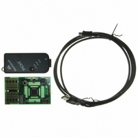
... MPLAB IDE On-line Help 4.2 PICkit 2 DEBUG EXPRESS KIT CONTENTS The PICkit 2 Debug Express kit (DV164121) contains the following items: 1. The PICkit 2 Development Programmer/Debugger 2. USB cable 3. 44-Pin Demo Board with device* 4. PICkit 2 Starter Kit and MPLAB IDE CD-ROMs * The following boards may also be used to debug use the Low Pin Count Demo Board from the Starter Kit, the AC162061 ICD Header and AC164110 adapter will be required ...
Page 36
... For a list of these devices and the required ICD header board part number, please see the “Header Board Specification” (DS51292). The Header Board Specification is included on the PICkit 2 CD-ROM, and is available online at www.microchip.com. DS51553E-page 32 website or © 2008 Microchip Technology Inc. ...
Page 37
... Header may be debugged directly over the In-Circuit Serial-Programming™ (ICSP™) connections. The DM164120-2 44-Pin Demo Board with PIC16F887 is shown. © 2008 Microchip Technology Inc. USING THE PIC16F690 ICD HEADER BOARD AC164110 ICSP™ to RJ-11 Adapter Debug Target CONNECTING THE DEMO BOARD TO THE PICKIT™ 2 ...
Page 38
... File Register memory, and will halt execution when a specific File Register is read from or written to. This breakpoint may also be set so it will only halt when a specific value is read from or written to a register. Additionally, a DS51553E-page 34 CAUTION BREAKPOINTS DIALOG FOR PIC16F887 © 2008 Microchip Technology Inc. ...
Page 39
... CALL instruction. To prevent this, a NOP may be placed between the CALL instructions. Note that 16-bit devices will halt two instructions after the breakpoint instruction. © 2008 Microchip Technology Inc. ADVANCED BREAKPOINTS DIALOG DS51553E-page 35 ...
Page 40
... The source file used for the tutorial is installed with the PICkit 2 Programmer software. 4.5.1 Selecting the Device To select a device in MPLAB IDE: 1. Launch the MPLAB IDE application. 2. From the MPLAB IDE menu bar, select Configure>Select Device (Figure 4-5). FIGURE 4-5: DS51553E-page 36 ® MPLAB IDE MENU BAR © 2008 Microchip Technology Inc. ...
Page 41
... PICkit 2 debug toolbar will be added, (C) the Debugger menu will change to add PICkit 2 debug functions and (D) the Output window will display communication status between the PICkit 2 and the target board on the PICkit 2 tab. FIGURE 4- © 2008 Microchip Technology Inc. SELECT DEVICE DIALOG PICkit™ 2 DEBUG TOOL C D DS51553E-page 37 ...
Page 42
... The Project Wizard helps you set up a new project. 1. Select Project>Project Wizard to set up the project. The Project Wizard Welcome screen will display (Figure 4-9). Click Next to continue to Step One. FIGURE 4-9: DS51553E-page 38 PICkit™ 2 SETTINGS DIALOG PROJECT WIZARD WELCOME © 2008 Microchip Technology Inc. ...
Page 43
... MPASM assembler should be pointing to mpasmwin.exe. - MPLINK™ object linker should be pointing to mplink.exe. - MPLIB™ object librarian should be pointing to mplib.exe. Click Next to continue to Step Three. FIGURE 4-11: © 2008 Microchip Technology Inc. STEP ONE – SELECT DEVICE STEP TWO – SELECT LANGUAGE SUITE DS51553E-page 39 ...
Page 44
... STEP THREE – CREATE NEW PROJECT Other files can be added later. For projects containing more than one assembly file (e.g., multifile projects, C code project) you will also need to add a linker script file. See the language tool documentation for more details. © 2008 Microchip Technology Inc. ...
Page 45
... If needed, files can be added to or removed from the project using the Project Window. Right click on the file in the Project Window tree to display a pop-up menu with options that include adding or removing files. © 2008 Microchip Technology Inc. STEP FOUR – ADD FILES PROJECT WIZARD SUMMARY ...
Page 46
... Brown-Out Detect – BOD and SBOREN Disabled • Internal-External Switch Over Mode – Disabled • Monitor Clock Fail-safe – Disabled • Low-Voltage Program – Disabled DS51553E-page 42 PROJECT WINDOW FILE MENU OUTPUT WINDOW – BUILD THE PROJECT © 2008 Microchip Technology Inc. ...
Page 47
... PIC16F887 (target device) when the PICkit 2 is selected as a debugger. Debug code must be programmed into the target device to use the in-circuit debugging capabilities of the PICkit 2. FIGURE 4-18: © 2008 Microchip Technology Inc. CONFIGURATION BIT SETTINGS OUTPUT WINDOW – PROGRAM DEVICE FOR DEBUG DS51553E-page 43 ...
Page 48
... Either right click on the line to display a drop-down menu and select “Set Breakpoint” or double click on the line. A breakpoint symbol will appear next to the line as the letter solid red octagon, as shown in Figure 4-19. DS51553E-page 44 Run Halt Animate Step Into Step Over Step Out Reset Toolbar Buttons © 2008 Microchip Technology Inc. ...
Page 49
... Select View>Watch to open a new Watch window. This window will allow you to watch the A/D register value change as the program executes. The Watch dialog opens with the Watch 1 tab selected, as shown in Figure 4-21. © 2008 Microchip Technology Inc. SET BREAKPOINT Depending on the device, breakpoint halts may “skid” past the breakpoint location ...
Page 50
... Converter Module section, indicates that the last bit should be a ‘1’ (b’01000001’) to turn on the A/D module. To fix this bug, change: movlw 0x40 to movlw 0x41, as shown in Figure 4-23. DS51553E-page 46 NEW WATCH WINDOW ADD SFRs TO WATCH © 2008 Microchip Technology Inc. ...
Page 51
... The source code in this tutorial contained only one bug. However, real code may have more. Using MPLAB IDE with PICkit 2 debugging functions, you can successfully find and fix problems in your code. © 2008 Microchip Technology Inc. A/D MODULE CODE ADCON CORRECT VALUE ...
Page 52
... Select PICkit programmer in the Programmer>Select Programmer menu. 3. Optional: Set up the ID in Configure>ID Memory (Figure 4-25). FIGURE 4-25: 4. Set up the parameters for programming on the Programmer>Settings, Program tab. 5. Select Programmer>Program. Now the target will run independently. DS51553E-page 48 USER ID MEMORY © 2008 Microchip Technology Inc. ...
Page 53
... Verify that the device is a member of the currently active family displayed at the top of the Status window. Select the correct family from the Device Family menu if needed. See also the © 2008 Microchip Technology Inc. PICkit™ 2 USER’S GUIDE /V pin in accordance with the device data sheet. ...
Page 54
... PICkit 2 in accordance with Chapter 3. “Using In-Circuit Serial Programming™ (ICSP™)”. Make sure that V rise time longer than 500 μs. the V DD DS51553E-page 50 ® program? ? Error” or “V Error” the intended volt capacitance is not reducing © 2008 Microchip Technology Inc. ...
Page 55
... For 8-bit devices, try waiting at least 2 minutes before concluding the software has truly locked up. For 16-bit devices, try waiting 5 minutes for the operation to complete. © 2008 Microchip Technology Inc. pin in order to function properly. If not using a separate regulator to sup- Windows Error: Unrecognized USB of +4 ...
Page 56
... This program mode entry will usually get around the problem, but it requires that the target device be powered from the PICkit 2 unit V pin. DS51553E-page 52 pin. On the Low Pin Count and 28-pin Demo PP © 2008 Microchip Technology Inc. pin PP DD ...
Page 57
... On this tab, change the “DPI setting:” to “Normal size (96 DPI) 6. Click Apply, then the OK button to close the dialog. 7. Click OK to close the Display Properties dialog. It may be necessary to restart the PC for the changes to take effect. © 2008 Microchip Technology Inc. DS51553E-page 53 ...
Page 58
... PK2Error0008: Read failure (GetLastError) PK2Error0009: Write failure (GetLastError) Description: MPLAB IDE was unable to communicate with the PICkit 2. Possible causes include the PICkit 2 not enumerating properly on USB, a target board causing a USB overcurrent condition or problems with a USB hub. DS51553E-page 54 © 2008 Microchip Technology Inc. ...
Page 59
... Try rebooting your system to free up memory. 2. Make sure you have a reasonable amount of free space on your hard drive, and that it is not overly fragmented. 3. See PK2Error0002 Suggested Actions © 2008 Microchip Technology Inc. PK2Error0002 Suggested Actions. PK2Error0002 Suggested for a corrupted installation. Actions. ...
Page 60
... Description: The target power supply is outside the voltage range supported by PICkit 2 for the current device. This may be due to device Bulk Erase limitations or PICkit 2 hardware limitations. DS51553E-page 56 Actions. PK2Error0002 Suggested PK2Error0008 Suggested Actions. measured at X.XV which is outside the DD © 2008 Microchip Technology Inc. Actions. ...
Page 61
... See Section 4.3 “Installing the Hardware and Software”. 5. The target board is not powered or is not powered properly. Check the power supply. 6. The PICkit 2 V © 2008 Microchip Technology Inc. voltage within the given range. If the target V DD load. DD and AV pins, check that these are properly connected ...
Page 62
... If the target device has AV are properly connected. Verify that PIC18FXXJXX, PIC24X, and dsPIC33F devices DS51553E-page 58 supply. DD ® DSC devices, the incorrect PGXn/EMUXn port is selected PK2Error0028 Suggested PK2Error0028 Suggested Actions. Actions. and AV pins, check that these DD SS © 2008 Microchip Technology Inc. ...
Page 63
... PK2Error0045: No STATSTG PK2Error0046: Failed IStream Read PK2Error0047: Failed Stream Write Description: PICkit 2 Debug Express internal error. Suggested Actions: This is likely caused by an incomplete or corrupted installation. See PK2Error0002 Suggested © 2008 Microchip Technology Inc. /V pin in accordance with the DDCORE CAP Actions. Actions. ...
Page 64
... NOTES: DS51553E-page 60 © 2008 Microchip Technology Inc. ...
Page 65
... Download the latest PICkit 2 firmware/OS from the Microchip web site at www.microchip.com default, the location is: C:\Program Files\Microchip\PICkit 2 v2 © 2008 Microchip Technology Inc. PICkit™ 2 USER’S GUIDE UPDATE PICkit™ WARNING and place the file in the PICkit 2 installation directory. By DS51553E-page 61 ...
Page 66
... C:\Program Files\Microchip\MPLAB IDE\PICkit 2 2. Select PICkit 2 as the debug tool (Debugger>Select Tool>PICkit 2) or program- mer (Programmer>Select Programmer>PICkit 2). DS51553E-page 62 DOWNLOAD PICkit™ UPDATE PICkit™ PROGRESS and place the file in the PICkit 2 installation directory. By © 2008 Microchip Technology Inc. ...
Page 67
... Busy LED on the PICkit 2 will flash. When the update completes suc- cessfully, the text in the PICkit 2 tab will state that “PICkit 2 Ready” and the Busy LED will go out. The firmware/OS update is then complete. © 2008 Microchip Technology Inc. DOWNLOAD PICkit™ FROM MPLAB ® ...
Page 68
... NOTES: DS51553E-page 64 © 2008 Microchip Technology Inc. ...
Page 69
... The PICkit 2 UART Tool will work with target V FIGURE 7-1: * The 6-pin header (0.100" spacing) accepts 0.025" square pins. © 2008 Microchip Technology Inc. PICkit™ 2 USER’S GUIDE pin must be connected to the target V DD voltages from 2.5 Volts to 5.0 Volts. ...
Page 70
... The mode selection affects how serial data is displayed and entered in the window, and the modes are explained in the next two sections. DS51553E-page 66 ). The serial data format is always 8 data bits, DD voltage or it will not be able to DD CAUTION PICkit™ 2 UART TOOL WINDOW ASCII MODE , the PICkit 2 V pin DD DD © 2008 Microchip Technology Inc. ...
Page 71
... Any pasted data will immediately be transmitted out of PICkit 2. 3. Use the “String Macros” at the bottom of the window. © 2008 Microchip Technology Inc. BAUD RATE SELECTION CUSTOM 14400 BAUD RATE ...
Page 72
... Send next to it. A hex sequence may contain from bytes. The “Echo On” checkbox has no function in Hex mode. Data in the terminal display may be selected (highlighted) with the cursor and copied into the clipboard by right clicking and selecting Copy or pressing <Ctrl> + <c>. DS51553E-page 68 © 2008 Microchip Technology Inc. ...
Page 73
... Save. While the terminal display is being saved to the log file, the Log to File button will turn green and display the text “Logging Data…”. (Figure 7-6) FIGURE 7-6: © 2008 Microchip Technology Inc. PICKIT™ 2 UART TOOL WINDOW HEX MODE LOG TO FILE IS ACTIVE ...
Page 74
... If the PICkit 2 application is closed, the UART Tool settings, including String Macros and Hex Sequences, will be saved and restored for the next time the UART Tool is used. The terminal display buffer text and data is not saved when the application is closed. DS51553E-page 70 © 2008 Microchip Technology Inc. ...
Page 75
... Special Function Register window or in the Watch window. To Halt Animate, use the menu option Debugger>Halt, the toolbar Halt or <F5>. Halt F5 Halt (stop) the execution of program code. When you click Halt, status information is updated. © 2008 Microchip Technology Inc. PICkit™ 2 USER’S GUIDE DS51553E-page 71 ...
Page 76
... A.2.2 Right Mouse Button Menu The following will appear on the right mouse menus in code displays, such as program memory and source code files: Set/Remove Breakpoint Set or remove a breakpoint at the currently selected line. DS51553E-page 72 © 2008 Microchip Technology Inc. ...
Page 77
... Configuration bits. Blank Check Check to see that all device memory is erased/blank. Read EEDATA Read EEDATA memory. Connect Establish communications between the PICkit 2 and the PC. Download OS Download PICkit 2 operating system/firmware. Release from Reset Set MCLR to V © 2008 Microchip Technology Inc DS51553E-page 73 ...
Page 78
... Verify that target memories are erased Check to see that all device memory is erased/blank. Release from Reset Set the target MCLR pin to V Hold in Reset Set the target MCLR pin to V Connect Establish communications between the PICkit 2 and the PC. DS51553E-page © 2008 Microchip Technology Inc. ...
Page 79
... This tab of the PICkit 2 Settings dialog allows you to enable or disable warning messages displayed in the Output window. • To enable/disable specific messages, click the check box next to the message to check/uncheck it. • To enable/disable all messages, click Check All/Uncheck All. © 2008 Microchip Technology Inc. PICkit™ 2 When is selected as the programmer, immediately attempt to connect. ...
Page 80
... NOTES: DS51553E-page 76 © 2008 Microchip Technology Inc. ...
Page 81
... Appendix B. PICkit 2 Schematics PICkit 2 Development Programmer/Debugger schematic diagrams are shown here. Demo board schematics are found in their respective user’s guides. FIGURE B-1: © 2008 Microchip Technology Inc. PICkit™ 2 USER’S GUIDE PICkit™ 2 SCHEMATIC DIAGRAM (PAGE DS51553E-page 77 ...
Page 82
... FIGURE B-2: DS51553E-page 78 PICkit™ 2 SCHEMATIC DIAGRAM (PAGE _TGT DD V © 2008 Microchip Technology Inc. ...
Page 83
... Erase....................................................... 11 Explorer 16............................................................... 31 Export Hex ............................................................... 11 F Fast Programming ................................................... 12 File History ............................................................... 11 Firmware .................................................................. 12 Firmware, Update .................................................... 61 Force PICkit 2 .......................................................... 12 Force Target ............................................................ 12 © 2008 Microchip Technology Inc. PICkit™ 2 USER’S GUIDE Index H Halt........................................................................... 71 Hex File, Import........................................................ 19 Hold Device in Reset................................................ 11 Hold in Reset............................................................ 74 I ICSP......................................................................... 27 ICSPCLK/ICSPDAT ................................................. 28 ...
Page 84
... Update Operating System ........................................ 61 USB Port .................................................................... 8 Use VPP First Program Entry................................... 12 V Vdd .................................................... 13 Verify .......................................................11 Verify Erased............................................................ 74 Verify on Write.......................................................... 11 Vpp ..................................................................... 28 Vss ........................................................................... 30 W Warning Messages................................................... 75 Warnings tab ............................................................ 75 Warranty Registration................................................. 4 Web Site, Microchip ................................................... 5 Write ......................................................................... 20 Write Device ............................................................. 11 Write on PICkit Button .............................................. 11 DS51553E-page © 2008 Microchip Technology Inc. ...
Page 85
... NOTES: © 2008 Microchip Technology Inc. DS51553E-page 81 ...
Page 86
... Fax: 886-3-572-6459 Taiwan - Kaohsiung Tel: 886-7-536-4818 Fax: 886-7-536-4803 Taiwan - Taipei Tel: 886-2-2500-6610 Fax: 886-2-2508-0102 Thailand - Bangkok Tel: 66-2-694-1351 Fax: 66-2-694-1350 © 2008 Microchip Technology Inc. EUROPE Austria - Wels Tel: 43-7242-2244-39 Fax: 43-7242-2244-393 Denmark - Copenhagen Tel: 45-4450-2828 Fax: 45-4485-2829 France - Paris Tel: 33-1-69-53-63-20 ...