ULINKPRO Keil, ULINKPRO Datasheet - Page 138
ULINKPRO
Manufacturer Part Number
ULINKPRO
Description
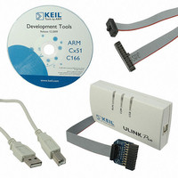
KIT DEBUG/TRACE UNIT HIGH SPEED
Manufacturer
Keil
Type
In-Circuit, Real-Time Debugger/Programmerr
Specifications of ULINKPRO
Contents
Module
For Use With/related Products
ARM7, ARM9, Cortex
Lead Free Status / RoHS Status
Lead free / RoHS Compliant


Getting Started: Creating Applications with µVision
Using the Logic Analyzer
The µVision Debugger includes a configurable Logic Analyzer you can use to
trace simulated signals and variables during program execution.
Add a number of signals to the Logic
Analyzer, including the simulated
A/D input signal.
Click the Setup button in the Logic
Analyzer Window to open the Setup
dialog. Press the
ADC1_IN1
input signal for A/D Channel 1, and
close the Setup dialog. You may
prefer to just drag and drop the object
from the Symbols Window into the
Logic Analyzer Window.
For complex analysis, multiple signals
can be selected and recorded. Save
and load the signal definitions using
the Export Signal Definitions…
and Import Signal
Definitions… button.
Run the program, and use the
Analog1 0..3 button of the
Toolbox to start changing the
signal on Analog Input 1.
Changes applied to the analog
inputs are reflected in the Logic
Analyzer.
1
The additional signals used in this screenshot are not integrated into the Measure example.
Open the Logic Analyzer Window
from the Debug Toolbar or View Menu
1
, which is the name of the
Ins
key, enter
137
Related parts for ULINKPRO
Image
Part Number
Description
Manufacturer
Datasheet
Request
R

Part Number:
Description:
MCU, MPU & DSP Development Tools USB-JTAG Adapter
Manufacturer:
Keil Tools

Part Number:
Description:
KEIL C-COMPILER INTERNATIONAL
Manufacturer:
Silicon Laboratories Inc
Part Number:
Description:
KEIL C-COMPILER US VERSION
Manufacturer:
Silicon Laboratories Inc

Part Number:
Description:
DEV KIT FOR STM32
Manufacturer:
STMicroelectronics
Datasheet:

Part Number:
Description:
KIT STARTER FOR STM32
Manufacturer:
STMicroelectronics
Datasheet:

Part Number:
Description:
KIT STARTER FOR STM32F10XE MCU
Manufacturer:
STMicroelectronics
Datasheet:

Part Number:
Description:
KIT STARTER KEIL FOR STR910
Manufacturer:
STMicroelectronics
Datasheet:


Part Number:
Description:
Microcontroller Modules & Accessories KEIL ULINK PRO 5V ADAPTOR KIT
Manufacturer:
Keil Software
Part Number:
Description:
Development Boards & Kits - ARM KEIL NUVOTON EVAL BD CORTEX-M0 + ULINK-ME
Manufacturer:
Keil Tools
Datasheet:
Part Number:
Description:
Development Boards & Kits - ARM KEIL NUVOTON EVAL BD CORTEX-M0
Manufacturer:
Keil Tools
Datasheet:

Part Number:
Description:
BOARD EVAL FOR LPC213X ARM MCU
Manufacturer:
NXP Semiconductors
Datasheet:

Part Number:
Description:
K60N512 Keil Tower Kit
Manufacturer:
Freescale Semiconductor
Datasheet: