USB-RS485-PCBA FTDI, Future Technology Devices International Ltd, USB-RS485-PCBA Datasheet - Page 10
USB-RS485-PCBA
Manufacturer Part Number
USB-RS485-PCBA
Description
MODULE USB-RS485
Manufacturer
FTDI, Future Technology Devices International Ltd
Series
USBmadeEZ-UARTr
Datasheet
1.USB-RS485-PCBA.pdf
(17 pages)
Specifications of USB-RS485-PCBA
Convert From (adapter End)
USB-A Male
Convert To (adapter End)
PCB
Features
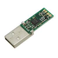
USB to RS485 Adapter PCB Assy w/ Embedded Controller and LEDs, 3MBaud
For Use With/related Products
Windows® 2000 or higher, Linux, Max OS X
Lead Free Status / RoHS Status
Lead free / RoHS Compliant
Other names
768-1043


4.2
Parameter
Table 4.2 USB-RS485-PCB
Parameter
Receiver Input
Transmitter Output
Table 4.4 USB-RS485-PCB I/O Pin Characteristics
* -
transmission line and the input impedance of 32 receivers on the line.
VCC_5V
VIHYST
VOD
VCM
VTH
RIN
The 54 ohms is the equivalent of two 120 ohm termination resistors placed on each side of the
IN
I
T
O
USB-RS485-PCB Electrical Parameters
Description
Output Power Voltage*
Output Power Current***
Operating Temperature
Range
Description
Common-mode input
voltage range
Input Current
Differential Threshold
Voltage,VTH
Input Hysteresis
Input Resistance, RIN
Differential Output Voltage,
dVOD
Copyright © 2010 Future Technology Devices International Limited
Minimum
Minimum
4.25
-0.2
-40
1.5
12
-7
-
Typical
Typical
5.0*
20
15
USB to RS485 UART Serial Converter PCB
Maximum
Maximum
+0.2
5.25
–0.8
+85
+12
250
1.0
5
Units
Units
mA
mA
mV
kΩ
o
V
V
V
V
C
Document Reference No.: FT_000120
*Default is GND. This figure
only applies when cable has
been customised to output
+5V. The range is
dependent on the USB port
that the USB-RS485-PCB is
connected to.
VIN = +12V
VIN = –7V
With RL = 54Ω. CL = 50pF *
POWER output is customised
Must be less that 2.5mA
***Only applies when
during suspend.
Conditions
Conditions
to +5V.
Clearance No. FTDI#80
Version 1.1
9
Datasheet
Related parts for USB-RS485-PCBA
Image
Part Number
Description
Manufacturer
Datasheet
Request
R

Part Number:
Description:
MODULE USB - RS485 WITH CABLE
Manufacturer:
FTDI, Future Technology Devices International Ltd
Datasheet:

Part Number:
Description:
MODULE USB - RS485
Manufacturer:
FTDI, Future Technology Devices International Ltd
Datasheet:

Part Number:
Description:
MODULE USB TO RS485 CONV SGL
Manufacturer:
FTDI, Future Technology Devices International Ltd
Datasheet:

Part Number:
Description:
MODULE USB TO RS485 CONV DUAL HS
Manufacturer:
FTDI, Future Technology Devices International Ltd
Datasheet:

Part Number:
Description:
MODULE USB TO RS485 CONV QUAD HS
Manufacturer:
FTDI, Future Technology Devices International Ltd
Datasheet:

Part Number:
Description:
KIT REF DES USB MASS STORAGE
Manufacturer:
Silicon Laboratories Inc
Datasheet:

Part Number:
Description:
Interface Modules & Development Tools USB HS to RS422 Conv Assembly 4 DB9 Ports
Manufacturer:
FTDI
Datasheet:

Part Number:
Description:
Interface Modules & Development Tools USB to RS422 Convrtr Assembly 1 DB9 Port
Manufacturer:
FTDI
Datasheet:

Part Number:
Description:
Interface Modules & Development Tools USB HS to RS485 Conv Assembly 4 DB9 Ports
Manufacturer:
FTDI
Datasheet:

Part Number:
Description:
Interface Modules & Development Tools USB HS to RS485 Conv Assembly 2 DB9 Ports
Manufacturer:
FTDI
Datasheet:

Part Number:
Description:
IC USB TO SERIAL UART 32-QFN
Manufacturer:
FTDI, Future Technology Devices International Ltd

Part Number:
Description:
IC USB HOST CTLR VINCULUM 48LQFP
Manufacturer:
FTDI, Future Technology Devices International Ltd
Datasheet:

Part Number:
Description:
IC USB HOST VINCULUM-II 32QFN
Manufacturer:
FTDI, Future Technology Devices International Ltd
Datasheet:
Part Number:
Description:
IC USB HOST VINCULUM-II 32LQFN
Manufacturer:
FTDI, Future Technology Devices International Ltd
Datasheet:
Part Number:
Description:
IC USB HOST VINCULUM-II 48QFN
Manufacturer:
FTDI, Future Technology Devices International Ltd
Datasheet: