USB-RS485-PCBA FTDI, Future Technology Devices International Ltd, USB-RS485-PCBA Datasheet - Page 15
USB-RS485-PCBA
Manufacturer Part Number
USB-RS485-PCBA
Description
MODULE USB-RS485
Manufacturer
FTDI, Future Technology Devices International Ltd
Series
USBmadeEZ-UARTr
Datasheet
1.USB-RS485-PCBA.pdf
(17 pages)
Specifications of USB-RS485-PCBA
Convert From (adapter End)
USB-A Male
Convert To (adapter End)
PCB
Features
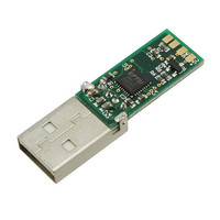
USB to RS485 Adapter PCB Assy w/ Embedded Controller and LEDs, 3MBaud
For Use With/related Products
Windows® 2000 or higher, Linux, Max OS X
Lead Free Status / RoHS Status
Lead free / RoHS Compliant
Other names
768-1043


Appendix A – PCB EEPROM Configuration
Each USB-RS485-PCB is controlled by the FTDI FT232R IC. This FT232R device contains an EEPROM which
contains the USB configuration descriptors for that device. When the PCB is plugged into a PC or a USB
reset is performed, the PC will read these descriptors. The default values stored into the internal EEPROM
are defined in Table 0.1 Default Internal EEPROM Configuration
Parameter
USB Vendor ID (VID)
USB Product UD (PID)
Serial Number Enabled?
Serial Number
Pull down I/O Pins in USB
Suspend
Manufacturer Name
Product Description
Max Bus Power Current
Power Source
Device Type
USB Version
Remote Wake Up
High Current I/Os
Load VCP Driver
Invert TXD
Invert RXD
Invert RTS#
Invert CTS#
Table 0.1 Default Internal EEPROM Configuration
The internal EEPROM on the PCB can be re-programmed over USB using the utility program MPROG.
MPROG can be downloaded from the www.ftdichip.com. Version 2.8a or later is required for the FT232R
chip. Users who do not have their own USB Vendor ID but who would like to use a unique Product ID in
their design can apply to FTDI for a free block of unique PIDs. Contact FTDI support for this service.
Copyright © 2010 Future Technology Devices International Limited
Bus Powered
See Note
See note
Disabled
Disabled
Disabled
Disabled
Disabled
Disabled
Enabled
Enabled
FT232R
0403h
6001h
90mA
Value
0200
FTDI
Yes
FTDI default VID (hex)
FTDI default PID (hex)
A unique serial number is generated and programmed into
the EEPROM during device final test.
Enabling this option will make the device pull down on the
UART interface lines when the power is shut off (PWREN#
is high).
USB-RS485-PCB
Returns USB 2.0 device description to the host.
Note: The device is be a USB 2.0 Full Speed device
(12Mb/s) as opposed to a USB 2.0 High Speed device
(480Mb/s).
Enables the high drive level on the UART and CBUS I/O
pins.
Makes the device load the VCP driver interface for the
device.
Signal on this pin becomes TXD# if enable.
Signal on this pin becomes RXD# if enable.
Signal on this pin becomes RTS if enable.
Signal on this pin becomes CTS if enable.
USB to RS485 UART Serial Converter PCB
Notes
Document Reference No.: FT_000120
Clearance No. FTDI#80
14
Version 1.1
Datasheet
Related parts for USB-RS485-PCBA
Image
Part Number
Description
Manufacturer
Datasheet
Request
R

Part Number:
Description:
MODULE USB - RS485 WITH CABLE
Manufacturer:
FTDI, Future Technology Devices International Ltd
Datasheet:

Part Number:
Description:
MODULE USB - RS485
Manufacturer:
FTDI, Future Technology Devices International Ltd
Datasheet:

Part Number:
Description:
MODULE USB TO RS485 CONV SGL
Manufacturer:
FTDI, Future Technology Devices International Ltd
Datasheet:

Part Number:
Description:
MODULE USB TO RS485 CONV DUAL HS
Manufacturer:
FTDI, Future Technology Devices International Ltd
Datasheet:

Part Number:
Description:
MODULE USB TO RS485 CONV QUAD HS
Manufacturer:
FTDI, Future Technology Devices International Ltd
Datasheet:

Part Number:
Description:
KIT REF DES USB MASS STORAGE
Manufacturer:
Silicon Laboratories Inc
Datasheet:

Part Number:
Description:
Interface Modules & Development Tools USB HS to RS422 Conv Assembly 4 DB9 Ports
Manufacturer:
FTDI
Datasheet:

Part Number:
Description:
Interface Modules & Development Tools USB to RS422 Convrtr Assembly 1 DB9 Port
Manufacturer:
FTDI
Datasheet:

Part Number:
Description:
Interface Modules & Development Tools USB HS to RS485 Conv Assembly 4 DB9 Ports
Manufacturer:
FTDI
Datasheet:

Part Number:
Description:
Interface Modules & Development Tools USB HS to RS485 Conv Assembly 2 DB9 Ports
Manufacturer:
FTDI
Datasheet:

Part Number:
Description:
IC USB TO SERIAL UART 32-QFN
Manufacturer:
FTDI, Future Technology Devices International Ltd

Part Number:
Description:
IC USB HOST CTLR VINCULUM 48LQFP
Manufacturer:
FTDI, Future Technology Devices International Ltd
Datasheet:

Part Number:
Description:
IC USB HOST VINCULUM-II 32QFN
Manufacturer:
FTDI, Future Technology Devices International Ltd
Datasheet:
Part Number:
Description:
IC USB HOST VINCULUM-II 32LQFN
Manufacturer:
FTDI, Future Technology Devices International Ltd
Datasheet:
Part Number:
Description:
IC USB HOST VINCULUM-II 48QFN
Manufacturer:
FTDI, Future Technology Devices International Ltd
Datasheet: