DM300014 Microchip Technology, DM300014 Datasheet
DM300014
Specifications of DM300014


Related parts for DM300014

DM300014 Summary of contents
Page 1
... Microchip Technology Inc. dsPICDEM™ 1.1 Development Board User’s Guide Advance Information DS70099B ...
Page 2
... Serialized Quick Turn Programming (SQTP service mark of Microchip Technology Incorporated in the U.S.A. All other trademarks mentioned herein are property of their respective companies. © 2003, Microchip Technology Incorporated, Printed in the U.S.A., All Rights Reserved. Printed on recycled paper. Microchip received ISO/TS-16949:2002 quality system certification for ...
Page 3
... Board Self-Test Code Module Summary ...................................................... 40 Chapter 4. dsPICDEM™ 1.1 Development Hardware 4.1 dsPICDEM 1.1 Development Board Hardware Overview ............................ 41 Appendix A. Hardware Drawings and Schematics A.1 Introduction .................................................................................................. 47 A.2 Highlights ..................................................................................................... 47 2003 Microchip Technology Inc. DEVELOPMENT BOARD Table of Contents Advance Information dsPICDEM™ 1.1 USER’S GUIDE ...
Page 4
... Development Board User’s Guide Appendix B. LCD Controller Specification B.1 Overview ...................................................................................................... 55 B.2 LCD Controller Interface .............................................................................. 55 B.3 Commands ................................................................................................... 56 B.4 General Commands ..................................................................................... 58 B.5 Character Commands .................................................................................. 59 B.6 Pixel Commands .......................................................................................... 61 B.7 Column Commands ..................................................................................... 62 B.8 Examples ..................................................................................................... 63 Index .............................................................................................................................65 Worldwide Sales and Service .....................................................................................68 DS70099B-page iv Advance Information 2003 Microchip Technology Inc. ...
Page 5
... Index – This section provides cross-reference listing of terms, features and sections of this document. • Worldwide Sales and Service – A listing of Microchip sales and service locations and telephone numbers worldwide. 2003 Microchip Technology Inc. DEVELOPMENT BOARD Preface Advance Information dsPICDEM™ 1.1 USER’ ...
Page 6
... The revision level of the document. Advance Information Examples #define START c:\autoexec.bat pic30-as [main.s] errorlevel {0|1} " " filename list " [ list_option..., " " list_option ] 0xFFFF, 0x007A char isascii (char, ch); File > Save OK, Cancel <Tab>, <Ctrl-C> MPLAB IDE User’s Guide 2003 Microchip Technology Inc. ...
Page 7
... For detailed information about any of the functionality, refer to the dsPIC30F Family Reference Manual (DS70046). MPLAB ASM30, MPLAB LINK30 and Utilities User’s Guide (DS51317) This document details Microchip Technology’s language tools for dsPIC devices based on GNU technology. The language tools discussed are: • MPLAB ASM30 Assembler • ...
Page 8
... Links to other useful web sites related to Microchip products Engineer’s Toolbox • Design Tips • Device Errata Other Available Information • Latest Microchip Press Releases • Listing of seminars and events • Job Postings DS70099B-page 4 ® ® or Microsoft Advance Information Internet Explorer. 2003 Microchip Technology Inc. ...
Page 9
... MPLAB IDE, MPLAB SIM and MPLAB SIM30 simulators, MPLAB IDE Project Manager and general editing and debugging features. Programmers – The latest information on Microchip device programmers. These include the PRO MATE programmer. 2003 Microchip Technology Inc. ® II device programmer and PICSTART Advance Information Preface ® ...
Page 10
... Microchip’s development systems software products. Plus, this line provides information on how customers can receive any currently available upgrade kits. The Hotline Numbers are: 1-800-755-2345 for U.S. and most of Canada. 1-480-792-7302 for the rest of the world. DS70099B-page 6 Advance Information 2003 Microchip Technology Inc. ...
Page 11
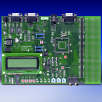
... The dsPICDEM 1.1 Printed Circuit Board (Figure 1-1) • Preprogrammed dsPIC30F6014 Plug-in Module (Figure 1-2) • Power Supply • RS-232 Interface Cable • dsPICDEM 1.1 Development Board Kit CD containing demonstration programs FIGURE 1- 2003 Microchip Technology Inc. DEVELOPMENT BOARD ds PICDEM 1.1 Demonstration Program ds PICDEM 1.1 DEVELOPMENT BOARD ...
Page 12
... Two RS-232 communication channels • 6-pin terminal block and configuration jumper for RS-485 and RS-422 communication on UART1 from the dsPIC device • Single CAN communication channel DS70099B-page 8 dsPIC30F6014 PLUG-IN MODULE and Advance Information with direct input from 9V, 2003 Microchip Technology Inc. ...
Page 13
... Four push button switches (SW1-SW4) for external input stimulus • 122 x 32 dot addressable LCD • PIC18F242 LCD controller • prototyping header for user hardware expansion (header not installed) • Prototype area for user hardware 2003 Microchip Technology Inc. Advance Information Introduction DS70099B-page 9 ...
Page 14
... MPLAB ICE Emulator User’s Guide (DS51159) You can obtain these reference documents from your nearest Microchip sales office (listed in the back of this document) or you can download them from the Microchip web site (www.microchip.com). DS70099B-page 10 Advance Information 2003 Microchip Technology Inc. ...
Page 15
... A workspace contains one or more projects and information on the selected device, debug tool and/or programmer, open windows and their location, and other IDE configuration settings. 2003 Microchip Technology Inc. DEVELOPMENT BOARD Chapter 2. Tutorial Advance Information dsPICDEM™ ...
Page 16
... From the Welcome screen, click Next> to display the Project Wizard Step One dialog (see Figure 2-1). FIGURE 2-1: 5. From the Device: pull-down list, select dsPIC30F6014 and click Next>. The Project Wizard Step Two dialog displays (see Figure 2-2). DS70099B-page 12 PROJECT WIZARD, STEP 1, SELECT A DEVICE Advance Information 2003 Microchip Technology Inc. ...
Page 17
... Click Next> to continue. The Project Wizard Step Three dialog displays (see Figure 2-3). Note: The tool locations for your environment may be different from those shown in this tutorial. 2003 Microchip Technology Inc. PROJECT WIZARD, STEP 2, SELECT LANGUAGE TOOLSUITE Advance Information Tutorial ...
Page 18
... In the Project Name text box, type MyProject. 2. Click Browse... and navigate to C:\Tutorial to place your project in the Tutorial folder. 3. Click Next> to continue. The Project Wizard Step Four dialog displays (see Figure 2-4). DS70099B-page 14 PROJECT WIZARD, STEP 3, NAME YOUR PROJECT Advance Information 2003 Microchip Technology Inc. ...
Page 19
... After the project wizard completes, the MPLAB IDE project window shows the Tut6014.s file in the Source Files folder and the p30f6014.gld file in the Linker Scripts folder (see Figure 2-5). 2003 Microchip Technology Inc. PROJECT WIZARD, STEP 4, ADD FILES TO PROJECT Advance Information ...
Page 20
... Tut6014.s file in the project window to open the file. MPLAB IDE should now look similar to Figure 2-6. FIGURE 2-6: Project Window Output Window DS70099B-page 16 MPLAB IDE PROJECT WINDOW MPLAB IDE WORKSPACE WINDOWS Advance Information Source Code Window 2003 Microchip Technology Inc. ...
Page 21
... Special Function Register (SFR) labels already defined for convenience. To build the code, select Build Options>Project from the Project> menu. The Build Options dialog displays, as shown in Figure 2-7. FIGURE 2-7: 2003 Microchip Technology Inc. BUILD OPTIONS Browse to the location of the assembler Include file ...
Page 22
... Click OK. The text box closes while the linker reserves space for the debug code used by the MPLAB ICD 2. 4. Click OK again to save these changes. The project is now ready to build. FIGURE 2-8: DS70099B-page 18 MPLAB LINK30 BUILD OPTIONS Check Link for ICD2 Advance Information 2003 Microchip Technology Inc. ...
Page 23
... Use the Configure>Configuration Bits menu to display the configuration settings. 2. Set up the configuration bits as shown in Figure 2-10. FIGURE 2-10: The highlighted configuration settings may need to change to the these values: Primary Oscillator Mode: Watchdog Timer: 2003 Microchip Technology Inc. BUILD OUTPUT WINDOW CONFIGURATION SETTINGS XT w/PLL 4x Disabled Advance Information ...
Page 24
... MPLAB ICD 2 is being used with a dsPIC30F device. Allow so. If any errors are shown, double-click the error message to get more information. DS70099B-page 20 On PGD/EMUD, PGC/EMUC MCLR1 On dsPICDEM 1.1 DEVELOPMENT BOARD CONNECTED TO MPLAB ICD 2 IN-CIRCUIT DEBUGGER Advance Information 2003 Microchip Technology Inc. ...
Page 25
... Select Allow ICD 2 to select memories and ranges, as shown in Figure 2-13. This setting will speed up operations by programming only a small part of the total program memory. FIGURE 2-13: 2003 Microchip Technology Inc. ENABLING MPLAB ICD 2 Status shows that target device has been found. ...
Page 26
... In addition, there are more functions available by right clicking on a line of source code. The most important of these are “Set Breakpoint” and “Run to Cursor.” DS70099B-page 22 PROGRAMMING THE dsPIC30F6014 DEVICE TUTORIAL LCD DISPLAY dsPICDEM 1.1 EVELOPMENT OARD D B UTORIAL T Advance Information 2003 Microchip Technology Inc. ...
Page 27
... The linker also provides values for the __SP_init and __SPLIM_init constants to initialize the stack pointer (W15), since the linker determines what RAM is available for the stack. 2003 Microchip Technology Inc. PROGRAM MEMORY WINDOW CODE START-UP mov #__SP_init, W15 ...
Page 28
... Press <F7> a few times and watch the values of TRISD and PORTD SFRs change. FIGURE 2-18: Note: The value displayed for PORTD may be different on your system depending on what load is on PORTD. DS70099B-page 24 SOURCE CODE WINDOW WATCH WINDOW DISPLAY Advance Information 2003 Microchip Technology Inc. ...
Page 29
... FIGURE 2-19: In this example, every time <F9> is pressed to run the code it sends one character to the display and stops at the breakpoint. After the first four spaces, the characters will start to appear on the LCD display. 2003 Microchip Technology Inc. btss flags, #0 SETTING BREAKPOINT ...
Page 30
... View the code execution in program memory and source code. • View registers in a Watch window. • Set a breakpoint and make the code halt at a chosen location. • Use the function keys to Reset, Run, Halt and Single-Step the code. DS70099B-page 26 Advance Information 2003 Microchip Technology Inc. ...
Page 31
... When power is applied to the dsPICDEM 1.1 Development Board, the LCD displays the Demo Main Menu, as shown in Figure 3-1. FIGURE 3-1: From this menu, pressing switch SW1 displays the menu options for the demonstration program, as shown in Figure 3-2. 2003 Microchip Technology Inc. DEVELOPMENT BOARD POWER-UP DISPLAY IT dsPIC30F 16-B ...
Page 32
... LCD display. DS70099B-page 28 DEMO MENU OPTIONS ENU PTIONS M O ATA CQ ISPLAY PERATIONS DSP O ENERATION DTMF G DATA ACQUISITION DISPLAY HZ EMP F = 1000 T = +23 V RP1 = 1.67 RP2 = 2.95 V RP3 = 2.62 MAIN – s1 Advance Information – S2 – S3 – 2003 Microchip Technology Inc. ...
Page 33
... Figure 3-5. HyperTerminal will show a composite display of the data acquisition values at an update rate of 1.14 seconds. FIGURE 3-5: To return to the Menu Options display after running the Data Acquisition demo, press switch SW1. 2003 Microchip Technology Inc. Demonstration Program Operation dsPICDEM™ 1.1 DEVELOPMENT BOARD TO PC CONNECTION J2 ...
Page 34
... T =018175 FILT =028649 MAIN CHNGFILT – s1 FREQUENCIES VS. POTENTIOMETER SETTING 0 ≤ RP1 ≤ ≤ RP1 ≤ ≤ RP1 ≤ ≤ RP1 ≤ ≤ RP1 ≤ 5V Advance Information = 032 – 2 Resulting Frequency 100 Hz 500 Hz 1000 Hz 1500 Hz 2000 Hz 2003 Microchip Technology Inc. ...
Page 35
... Generated Sinewave x Figure 3-8 shows the frequency response of the IIR filter implemented on the dsPIC30F. The IIR filter is only employed for demonstrating filter operation. FIGURE 3-8: 2003 Microchip Technology Inc. Demonstration Program Operation DSP OPERATIONS FLOW DIAGRAM Low-Pass Filter A/D Converter ...
Page 36
... PLAY SEQ MAIN –s4 DTMF TONE GENERATION CONTROLS Function Moves blinking cursor to the next DTMF Tone digit Plays the DTMF tone associated with the digit selected by s2 Plays a predetermined sequence of ten DTMF tones Advance Information –s1 2003 Microchip Technology Inc. ...
Page 37
... SPI 2 - Used to communicate to the 122 x 32 Addressable-Pixel LCD via the PIC18F242 LCD controller and MCP41010 digital potentiometer • 12-bit ADC - Used to convert multiple analog signals, including temperature and sinewave signals generated by the MCP41010 digital potentiometer through a low-pass filter 2003 Microchip Technology Inc. Demonstration Program Operation Advance Information DS70099B-page 33 ...
Page 38
... Configured to operate at 8000 Hz sampling rate and generate an interrupt every 16 sample-convert sequences. The ADC samples channel AN3 (sinewave), AN4 (RP2), AN5 (RP3), AN6 (RP1) and AN8 (temperature sensor U9). Peripheral interrupts are configured. Nested interrupts are enabled. Advance Information CY /32 Hz. 2003 Microchip Technology Inc. ...
Page 39
... The changes are communicated to the PIC18F242 LCD controller via the SPI 2 module the special case of the DTMF menu, the main routine may also kick off the DCI module operation when the user requests DTMF tone generation. 2003 Microchip Technology Inc. Demonstration Program Operation MAIN LOOP CODE EXECUTION SEQUENCE Program Task ...
Page 40
... When code execution reaches the DSP stage (i.e., filtering, FFT etc.) the SPI 2 module is used to send data to the PIC18F242 LCD controller on the expansion board at a data rate of 921.6 KHz (F display. All 80 characters are refreshed by the SPI 2 module. DS70099B-page 36 /8). The LCD has a 4 row x 20-character CY Advance Information 2003 Microchip Technology Inc. ...
Page 41
... Note: The demo code as supplied has specific timing parameters derived from the 7.3728 MHz crystal with the XTx4PLL mode. Changing the device time base will require modification of several time-specific parameters. 2003 Microchip Technology Inc. Demonstration Program Operation Advance Information DS70099B-page 37 ...
Page 42
... Adding these three major timing metrics results in 44.34 mS. Therefore, this 44.34 mS cycle is repeated 22.55 times second interval. Total MIPS required = 2.1 MIPS out of available 7.3728 MIPS. FIR filter specifications are listed in Table 3-5. DS70099B-page 38 Advance Information /8 Hz (where CY 2003 Microchip Technology Inc. ...
Page 43
... Passband ripple Stopband ripple Passband cutoff frequencies Stopband cutoff frequencies Sampling frequency The filter coefficients and code were generated by the Digital Filter Design Tool. 2003 Microchip Technology Inc. Demonstration Program Operation FIR FILTER SPECIFICATIONS BandPass Kaiser Window - 273 coefficients 0.001 dB ...
Page 44
... A running counter is sent to the MCP41010 digital potentiometer. The D POT value should be counting on the LCD. When pin J2-3 is connected to J5-2 and pin J2-2 is connected to J5-3, “OK” will appear on the lower right corner of the screen at power-up. DS70099B-page 40 Advance Information 2003 Microchip Technology Inc. ...
Page 45
... Si3000 Codec (Section 4.1.11) 9 Codec Reset Switch (Section 4.1.11) 10 Temperature Sensor (Section 4.1. Regulator (Section 4.1.13) Note 1: See Plug-in Module shown in Figure 4-2. 2003 Microchip Technology Inc. DEVELOPMENT BOARD dsPICDEM 1.1 DEVELOPMENT BOARD dsPICDEM 1.1 DEVELOPMENT BOARD HARDWARE Hardware Element No. 12 ...
Page 46
... The schematic of the CAN port is shown in Figure A-4: “dsPICDEM 1.1 Development Board Schematic (Sheet 3 of 5)”. DS70099B-page 42 DSPIC30F DEVICE PLUG-IN MODULE Match Pin 1 index marker of dsPIC30F device to lower left 45° corner of the 80-pin QFP footprint (pin 1 of Emulation Header). Advance Information 2003 Microchip Technology Inc. ...
Page 47
... Four red LEDs, LED1-LED4, are connected to port pins RD0-RD3, respectively, on the dsPIC device. The LED anodes are tied to V The schematic of the LEDs is shown in Figure A-6: “dsPICDEM 1.1 Development Board Schematic (Sheet 5 of 5)”. 2003 Microchip Technology Inc. through a 1.2 KOhm resistor. DD Advance Information ...
Page 48
... U6 socket. The CODEC RESET switch resets the Si3000. For detailed operational information, refer to the Si3000 data sheet available on www.silabs.com. For a schematic of the Si3000 circuit, see Figure A-5: “dsPICDEM 1.1 Development Board Schematic (Sheet 4 of 5)”. DS70099B-page 44 Advance Information 2003 Microchip Technology Inc. ...
Page 49
... Canned Oscillator (U5) RC External Clock The oscillator circuit schematics are shown in Figure A-2: “dsPICDEM 1.1 Development Board Schematic (Sheet 1 of 5)” 2003 Microchip Technology Inc. and AV ) are provided to their respective processor pins and DD OSCILLATOR SELECTION PARAMETERS Modifications on dsPICDEM 1.1 Demo Board R33, R34, R20, C20, C21 and X2 open, U5 empty ...
Page 50
... The pin 1 index marker of dsPIC30F device should align with the lower left 45° corner of the 80-pin QFP footprint (pin 1 of Emulation Header J14). Pin-out information for the emulation header is shown in Figure A-3: “dsPICDEM 1.1 Development Board Schematic (Sheet 2 of 5)”. DS70099B-page 46 Advance Information 2003 Microchip Technology Inc. ...
Page 51
... This Appendix provides a layout drawing of the printed circuit board followed by schematics for the dsPICDEM 1.1 Development Board. A.2 HIGHLIGHTS • dsPICDEM 1.1 Development Board Layout • dsPICDEM 1.1 Development Board Schematics 2003 Microchip Technology Inc. DEVELOPMENT BOARD Advance Information dsPICDEM™ 1.1 USER’S GUIDE DS70099B-page 47 ...
Page 52
... Development Board User’s Guide FIGURE A-1: DS70099B-page 48 dsPICDEM 1.1 DEVELOPMENT BOARD LAYOUT Advance Information 2003 Microchip Technology Inc. ...
Page 53
... FIGURE A-2: dsPICDEM 1.1 DEVELOPMENT BOARD SCHEMATIC (SHEET 2003 Microchip Technology Inc. Hardware Drawings and Schematics Advance Information DS70099B-page 49 ...
Page 54
... Development Board User’s Guide FIGURE A-3: dsPICDEM 1.1 DEVELOPMENT BOARD SCHEMATIC (SHEET DS70099B-page 50 Advance Information 2003 Microchip Technology Inc. ...
Page 55
... FIGURE A-4: dsPICDEM 1.1 DEVELOPMENT BOARD SCHEMATIC (SHEET 2003 Microchip Technology Inc. Hardware Drawings and Schematics Advance Information DS70099B-page 51 ...
Page 56
... Development Board User’s Guide FIGURE A-5: dsPICDEM 1.1 DEVELOPMENT BOARD SCHEMATIC (SHEET DS70099B-page 52 Advance Information 2003 Microchip Technology Inc. ...
Page 57
... FIGURE A-6: dsPICDEM 1.1 DEVELOPMENT BOARD SCHEMATIC (SHEET 2003 Microchip Technology Inc. Hardware Drawings and Schematics Advance Information DS70099B-page 53 ...
Page 58
... Development Board User’s Guide NOTES: DS70099B-page 54 Advance Information 2003 Microchip Technology Inc. ...
Page 59
... Thus, implementing flow control on the dsPIC device in all but the most unusual circumstances would be an unnecessary complication. 2003 Microchip Technology Inc. DEVELOPMENT BOARD ® nomenclature, the LCD controller is set slave Advance Information dsPICDEM™ ...
Page 60
... The LCD accommodates four character rows (0-3) and 20 character columns (0-19). Unless otherwise specified, incrementing ChrPosC beyond column 19 will wrap to the next row (i.e., ChrPosC = 0 and ChrPosR + 1). If ChrPosR exceeds 3, it will wrap to row 0. DS70099B-page 56 Advance Information 2003 Microchip Technology Inc. ...
Page 61
... PIC18F242 LCD controller requires adherence to this protocol: • Command name: Description • Cmd: Opcode value • Data: Number of data bytes - [ Command dependent data - [ Command dependent data - [ Command dependent data 2003 Microchip Technology Inc. LCD Controller Specification Advance Information DS70099B-page 57 ...
Page 62
... ScrollY = 8 but its location in the data array is still at 0). DS70099B-page 58 Form None Form None Form None Form Advance Information Value 0x80 None Value 0x81 None Value 0x82 None Value 0xA3 Y1 Y0 0-31 2003 Microchip Technology Inc. ...
Page 63
... The WrtChr command sets ChrPos to (ChrPosC,ChrPosR), then writes ASCII character to ChrPos. Field Opcode Data ChrPosC ChrPosR B.5.4 WrtChrInc Command The WrtChrInc command sets ChrPos to (ChrPosC,ChrPosR), writes an ASCII character to ChrPos, and then increments ChrPos. Field Opcode Data ChrPosC ChrPosR 2003 Microchip Technology Inc. LCD Controller Specification Form Form ...
Page 64
... A3 A2 Form Form None Form None Form None Form Advance Information Value 0xA8 A1 A0 ASCII character Value 0xA9 R1 R0 Row 0-3 Value 0x8A None Value 0x8B None Value 0x8C None Value 0xAD T1 T0 (0-7) x 0.125 seconds 2003 Microchip Technology Inc. ...
Page 65
... This command does not increment PixPos. Field Opcode PixPosX PixPosY B.6.4 PixLine Command The PixLine command draws a straight line from the current PixPos to the specified location and leaves PixPos set to the new location. Field Opcode PixPosX PixPosY 2003 Microchip Technology Inc. LCD Controller Specification Form ...
Page 66
... Field Opcode Column Data DS70099B-page 62 Form Form Form Form Form Advance Information Value 0xDB X1 X0 Column 0-121 R1 R0 Row 0-3 Value 0xBC D1 D0 Data Value 0xBD D1 D0 Data Value 0xBE D1 D0 Data Value 0xBF D1 D0 Data 2003 Microchip Technology Inc. ...
Page 67
... Write the following bytes to SPI port: 0xDB, 19, 1 0xBC, 0x01 0xBC, 0xFF 0xBC, 0x01 2003 Microchip Technology Inc. LCD Controller Specification WRITE A WORD // Clear screen // Write ‘H’ to column 10, row 2, then increment the column // Write ‘i’ at column 11, row 2 then increment the column ...
Page 68
... Development Board User’s Guide NOTES: DS70099B-page 64 Advance Information 2003 Microchip Technology Inc. ...
Page 69
... Demonstration Program Data Acquisition Display ................................... 28 DSP Operations Display ................................... 30 DTMF Tone Generation .................................... 32 Summary .......................................................... 27 Demonstration Programs ......................................... 10 Development Board Features Analog................................................................. 9 Device Clocking .................................................. 9 ICD 2 and ICE4000 Connections........................ 8 2003 Microchip Technology Inc. DEVELOPMENT BOARD Index Miscellaneous ..................................................... 9 Power Supply Circuit........................................... 8 Serial Communication Channels......................... Voice-band Codec .............................................. 9 Layout ............................................................... 48 Photograph ...
Page 70
... RS-485 Port........................................................ 41 S Sample Devices ....................................................... 46 Serial Communication Features ................................. 8 Si3000 Codec........................................................... 41 Si3000 External Clock Socket .................................. 41 Si3000 Voice-band Codec........................................ Source Code Window......................................... Temperature Sensor .......................................... 41 Test Code Module .................................................... Regulator .......................................................... 41 Voice-band Codec Features....................................... Warranty Registration................................................. 2 Watch Window ......................................................... 24 WWW Address ........................................................... Advance Information 2003 Microchip Technology Inc. ...
Page 71
... NOTES: 2003 Microchip Technology Inc. Advance Information Index DS70099B-page 67 ...
Page 72
... Via Quasimodo, 12 20025 Legnano (MI) Milan, Italy Tel: 39-0331-742611 Fax: 39-0331-466781 Netherlands Biesbosch 14 NL-5152 SC Drunen, Netherlands Tel: 31-416-690399 Fax: 31-416-690340 United Kingdom 505 Eskdale Road Winnersh Triangle Wokingham Berkshire, England RG41 5TU Tel: 44-118-921-5869 Fax: 44-118-921-5820 11/24/03 2003 Microchip Technology Inc. ...