DM300014 Microchip Technology, DM300014 Datasheet - Page 34
DM300014
Manufacturer Part Number
DM300014
Description
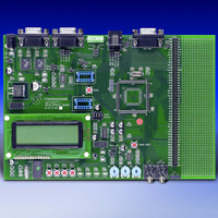
BOARD DEMO DSPICDEM 1.1 GEN PURP
Manufacturer
Microchip Technology
Datasheet
1.DM300014.pdf
(72 pages)
Specifications of DM300014
Processor To Be Evaluated
PIC30F
Data Bus Width
16 bit
Interface Type
RS-485, CAN, SPI
Lead Free Status / RoHS Status
Lead free / RoHS Compliant
Lead Free Status / RoHS Status
Lead free / RoHS Compliant, Lead free / RoHS Compliant


dsPICDEM™ 1.1 Development Board User’s Guide
DS70099B-page 30
3.3.1.2
From the Menu Options display, pressing switch SW3 launches the DSP Operations
demo, which displays the digital signal values shown in Figure 3-6. This display
provides information on the various signal-processing operations that are performed on
the signal at analog input pin, AN3.
FIGURE 3-6:
The DSP operations display shows several parameters for a sampled sinewave signal.
A fundamental sinewave signal is generated by stepping the MCP41010 digital
potentiometer (U9) output at an 8 kHz rate. The output of the digital potentiometer is
applied to a low-pass (LP) filter with a cutoff frequency of approximately 4 kHz. This LP
filter removes the high-frequency components and yields a sinewave adequate for this
demonstration. Five frequencies are developed and selected by varying potentiometer
RP1, as shown in Table 3-1.
TABLE 3-1:
The filtered output of the MCP41010 is routed to pin AN3/RB3, which is an input to the
dsPIC30F 12-bit A/D converter. The A/D converter collects 256 samples from the
MCP41010 at an 8 kHz sample rate. These samples are optionally subjected to a digital
filtering algorithm implemented on the dsPIC30F. The following three digital filtering
options are provided and selected by switch SW2:
• None
• Infinite Impulse Response (IIR)
• Finite Impulse Response (FIR)
Subsequently, their spectral components are estimated. The frequency estimate of the
signal on pin AN3/RB3 is displayed on the first row of the DSP Operations display.
DSP OPERATIONS MODE
Potentiometer Setting
0 ≤ RP1 ≤ 1V
1 ≤ RP1 ≤ 2V
2 ≤ RP1 ≤ 3V
3 ≤ RP1 ≤ 4V
4 ≤ RP1 ≤ 5V
FREQUENCIES VS. POTENTIOMETER SETTING
Advance Information
DSP OPERATIONS DISPLAY
F = 1000
256
I I R
MAIN
PT
– s1
T
T
FILT
FFT
CHNGFILT
=018175
=028649
B
IN
= 032
–
Resulting Frequency
CY
CY
S
2
2003 Microchip Technology Inc.
1000 Hz
1500 Hz
2000 Hz
100 Hz
500 Hz
Related parts for DM300014
Image
Part Number
Description
Manufacturer
Datasheet
Request
R

Part Number:
Description:
Manufacturer:
Microchip Technology Inc.
Datasheet:
Part Number:
Description:
Manufacturer:
Microchip Technology Inc.
Datasheet:
Part Number:
Description:
Manufacturer:
Microchip Technology Inc.
Datasheet:
Part Number:
Description:
Manufacturer:
Microchip Technology Inc.
Datasheet:
Part Number:
Description:
Manufacturer:
Microchip Technology Inc.
Datasheet:
Part Number:
Description:
Manufacturer:
Microchip Technology Inc.
Datasheet:
Part Number:
Description:
Manufacturer:
Microchip Technology Inc.
Datasheet:
Part Number:
Description:
Manufacturer:
Microchip Technology Inc.
Datasheet: