DM300014 Microchip Technology, DM300014 Datasheet - Page 50
DM300014
Manufacturer Part Number
DM300014
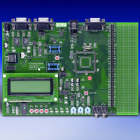
Description
BOARD DEMO DSPICDEM 1.1 GEN PURP
Manufacturer
Microchip Technology
Datasheet
1.DM300014.pdf
(72 pages)
Specifications of DM300014
Processor To Be Evaluated
PIC30F
Data Bus Width
16 bit
Interface Type
RS-485, CAN, SPI
Lead Free Status / RoHS Status
Lead free / RoHS Compliant
Lead Free Status / RoHS Status
Lead free / RoHS Compliant, Lead free / RoHS Compliant


dsPICDEM™ 1.1 Development Board User’s Guide
DS70099B-page 46
4.1.16
By placing J10 jumper in the MCLR1 position, the Reset switch connected to the
processor MCLR pin provides a hard RESET to the dsPIC device. By placing J10
jumper in the MCLR2 position, the Reset switch is connected to the PIC18F242 LCD
controller.
The Reset switch circuit is shown in Figure A-3: “dsPICDEM 1.1 Development Board
Schematic (Sheet 2 of 5)”.
4.1.17
A prototyping area and associated header are provided on the development board to
enable additional ICs and attachment boards to be added (see Figure
A-2: “dsPICDEM 1.1 Development Board Schematic (Sheet 1 of 5)”).
4.1.18
A sample dsPIC device programmed with the demonstration code is included in the
dsPICDEM 1.1 Development Board Kit. The 80-pin TQFP is soldered to a 1.5″ x 1.5″
adaptor PCB, which is inserted onto the emulation header, J11 and J13-J15.
Handle the device carefully when inserting and extracting the adaptor board. The
orientation of the adaptor board is important. The Microchip logo and device part
numbering should be aligned to read from left to right before insertion of the adaptor
board. The pin 1 index marker of dsPIC30F device should align with the lower left
45° corner of the 80-pin QFP footprint (pin 1 of Emulation Header J14).
Pin-out information for the emulation header is shown in Figure A-3: “dsPICDEM 1.1
Development Board Schematic (Sheet 2 of 5)”.
Reset Switch
Prototyping Area
Sample Devices
Advance Information
2003 Microchip Technology Inc.
Related parts for DM300014
Image
Part Number
Description
Manufacturer
Datasheet
Request
R

Part Number:
Description:
Manufacturer:
Microchip Technology Inc.
Datasheet:
Part Number:
Description:
Manufacturer:
Microchip Technology Inc.
Datasheet:
Part Number:
Description:
Manufacturer:
Microchip Technology Inc.
Datasheet:
Part Number:
Description:
Manufacturer:
Microchip Technology Inc.
Datasheet:
Part Number:
Description:
Manufacturer:
Microchip Technology Inc.
Datasheet:
Part Number:
Description:
Manufacturer:
Microchip Technology Inc.
Datasheet:
Part Number:
Description:
Manufacturer:
Microchip Technology Inc.
Datasheet:
Part Number:
Description:
Manufacturer:
Microchip Technology Inc.
Datasheet: