PMF18WD1 Microchip Technology, PMF18WD1 Datasheet - Page 33
PMF18WD1
Manufacturer Part Number
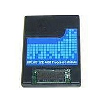
PMF18WD1
Description
PROCESSOR MODULE FOR ICE4000
Manufacturer
Microchip Technology
Datasheet
1.ICE4000.pdf
(98 pages)
Specifications of PMF18WD1
Module/board Type
Processor Module
Product
Microcontroller Modules
Core Processor
PIC18F1310 and PIC18F1320
Lead Free Status / RoHS Status
Contains lead / RoHS non-compliant
For Use With/related Products
ICE4000
For Use With
ICE4000 - EMULATOR MPLAB-ICE 4000 POD
Lead Free Status / RoHS Status
Lead free / RoHS Compliant, Contains lead / RoHS non-compliant


5.1
5.2
5.3
2004 Microchip Technology Inc.
INTRODUCTION
HIGHLIGHTS
PIC18F8XXX PROGRAM MEMORY MODES
Some Microchip devices allow the extension or replacement of program memory
resources with external (off-chip) memory devices. Of these devices, the MPLAB ICE
4000 supports PIC18F8XXX devices (but not PIC17CXXX devices.)
How the emulator functions for these modes is discussed here.
Topics covered in the chapter are:
• PIC18F8XXX Program Memory Modes
• Emulating PIC18F8XXX Program Memory Modes
• MPLAB IDE and External Memory
PIC18F8XXX devices are capable of operating in any one of several Program Memory
modes, using combinations of on-chip and external program memory. Available
Program Memory modes are as follows:
• The Microprocessor mode permits access only to external program memory; the
• The Microprocessor with Boot Block mode accesses on-chip Flash memory
• The Microcontroller mode accesses only on-chip Flash memory. Attempts to
• The Extended Microcontroller mode allows access to both internal and external
In all modes, the device has complete access to data RAM and EEPROM. For more
information, consult the device data sheet section “Memory Organization”.
Chapter 5. External Memory Usage
contents of the on-chip Flash memory are ignored. The program counter permits
access to a linear program memory space and defines the amount of accessible
program memory (see Section 5.3.1 “Program Counter”.)
from address 000000h to the end of the boot block. Above this, external program
memory is accessed all the way up to the program counter accessible limit (see
Section 5.3.1 “Program Counter”.) Program execution automatically switches
between the two memories, as required.
read above the physical limit of the on-chip Flash causes a read of all ‘0’s (a NOP
instruction.)
program memories as a single block. The device can access its entire on-chip
Flash memory; above this, the device accesses external program memory up to
the program counter accessible limit (see Section 5.3.1 “Program Counter”.) As
with Boot Block mode, execution automatically switches between the two memo-
ries, as required.
MPLAB
USER’S GUIDE
®
ICE 4000
DS51490A-page 27
Related parts for PMF18WD1
Image
Part Number
Description
Manufacturer
Datasheet
Request
R

Part Number:
Description:
Manufacturer:
Microchip Technology Inc.
Datasheet:
Part Number:
Description:
Manufacturer:
Microchip Technology Inc.
Datasheet:
Part Number:
Description:
Manufacturer:
Microchip Technology Inc.
Datasheet:
Part Number:
Description:
Manufacturer:
Microchip Technology Inc.
Datasheet:
Part Number:
Description:
Manufacturer:
Microchip Technology Inc.
Datasheet:
Part Number:
Description:
Manufacturer:
Microchip Technology Inc.
Datasheet:
Part Number:
Description:
Manufacturer:
Microchip Technology Inc.
Datasheet:
Part Number:
Description:
Manufacturer:
Microchip Technology Inc.
Datasheet: