PMF18WD1 Microchip Technology, PMF18WD1 Datasheet - Page 35
PMF18WD1
Manufacturer Part Number
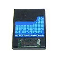
PMF18WD1
Description
PROCESSOR MODULE FOR ICE4000
Manufacturer
Microchip Technology
Datasheet
1.ICE4000.pdf
(98 pages)
Specifications of PMF18WD1
Module/board Type
Processor Module
Product
Microcontroller Modules
Core Processor
PIC18F1310 and PIC18F1320
Lead Free Status / RoHS Status
Contains lead / RoHS non-compliant
For Use With/related Products
ICE4000
For Use With
ICE4000 - EMULATOR MPLAB-ICE 4000 POD
Lead Free Status / RoHS Status
Lead free / RoHS Compliant, Contains lead / RoHS non-compliant


5.4
2004 Microchip Technology Inc.
EMULATING PIC18F8XXX PROGRAM MEMORY MODES
Emulating a device that uses external memory requires the following steps:
1. Setting Configuration Bits
2. Setting External Memory
3. Setting Memory Options
5.4.1
To set the values of configuration bits for your selected device, open the Configuration
Bits window by selecting Configure>Configuration Bits. In the Category column, find
Processor mode and select the mode.
5.4.2
To set up MPLAB IDE and MPLAB ICE 4000 to use external memory, select
Configure>External Memory. Then check “Use External Memory” and enter a range.
5.4.3
To set up memory options, open the Settings dialog (Debugger>Settings) and select
the Memory tab (Section 8.17 “Settings Dialog, Memory Tab”).
The Processor mode currently selected in the configuration bits will be reflected under
“Mode”. If the mode selected supports external memory, functions on this tab will be
active.
When emulating a Program Memory mode that makes use of external memory, two
choices are available:
• External Program Memory Supplied by Emulator – Use emulator memory for
• External Program Memory On Target Board – Use the emulator as a device
5.4.3.1
To use only emulator memory, select “Supplied by Emulator” under “External (Off-Chip)
Program Memory”. The amount of emulator-supplied memory will display in “Emulator
Supplied” under “ICE Memory Mapping”. “Target Supplied” should say “Not Used”.
If you still need to access a range of target memory to control external circuits, set up
a “Memory Mapped Peripheral Range”. Check the box “Enable Banked Access Mode”
and enter a target memory start and end address. This may either be a range within
the emulator range, or a range above this but below the program counter maximum
(see Section 5.3.1 “Program Counter”.)
both on-chip and off-chip (external) memory during development. This has the
advantage of speeding up program load time after a build. It has the disadvantage
of not actually using the target external memory.
would be used, with the emulator memory representing only on-chip memory. This
has the advantage of testing the application as it will actually be run, with external
memory. It has the disadvantage of longer upload/download times, as commands,
writes and reads to external memory will take time.
In order for the MPLAB ICE 4000 to load your code into external program mem-
ory, the target system must provide SRAM or DRAM. If the target system uses
non-volatile memory, such as Flash, the emulator will not be able to load code into
external memory. For non-volatile memory, you must provide an alternate method
of loading program memory. However, the emulator can upload non-volatile
memory and run from non-volatile memory.
Note: Configuration bits may also be set in code using __config. Refer to the
Setting Configuration Bits
Setting External Memory
Setting Memory Options
EXTERNAL PROGRAM MEMORY SUPPLIED BY EMULATOR
device data sheet and header file (.inc or .h) for more information.
External Memory Usage
DS51490A-page 29
Related parts for PMF18WD1
Image
Part Number
Description
Manufacturer
Datasheet
Request
R

Part Number:
Description:
Manufacturer:
Microchip Technology Inc.
Datasheet:
Part Number:
Description:
Manufacturer:
Microchip Technology Inc.
Datasheet:
Part Number:
Description:
Manufacturer:
Microchip Technology Inc.
Datasheet:
Part Number:
Description:
Manufacturer:
Microchip Technology Inc.
Datasheet:
Part Number:
Description:
Manufacturer:
Microchip Technology Inc.
Datasheet:
Part Number:
Description:
Manufacturer:
Microchip Technology Inc.
Datasheet:
Part Number:
Description:
Manufacturer:
Microchip Technology Inc.
Datasheet:
Part Number:
Description:
Manufacturer:
Microchip Technology Inc.
Datasheet: